Accelerometer

a technology of accelerometer and accelerometer body, which is applied in the direction of measuring devices, mechanically powered devices, instruments, etc., can solve the problems of detection limit, sensitivity, detection limit, etc., and achieve the effect of convenient fabrication and packaging

Active Publication Date: 2012-03-20
PHYSICAL LOGIC LTD
View PDF7 Cites 5 Cited by
  • Summary
  • Abstract
  • Description
  • Claims
  • Application Information

AI Technical Summary

Problems solved by technology

Such devices have inherent limitations on the minimum size, detection limit, sensitivity and the like, largely due to the means used for detecting the deflection of the proof mass.

Method used


Image

  • Accelerometer
  • Accelerometer
  • Accelerometer

Examples


Embodiment Construction

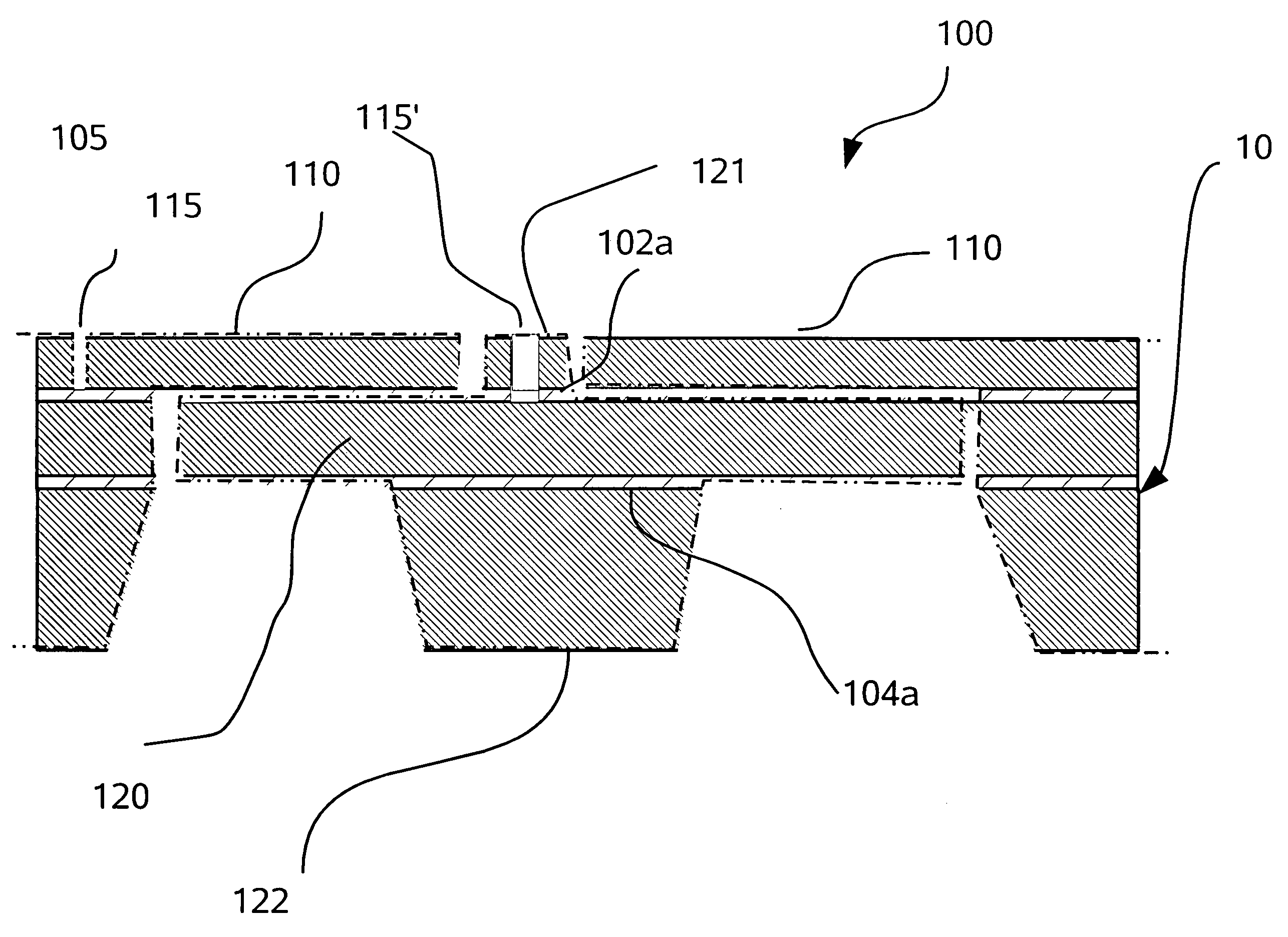
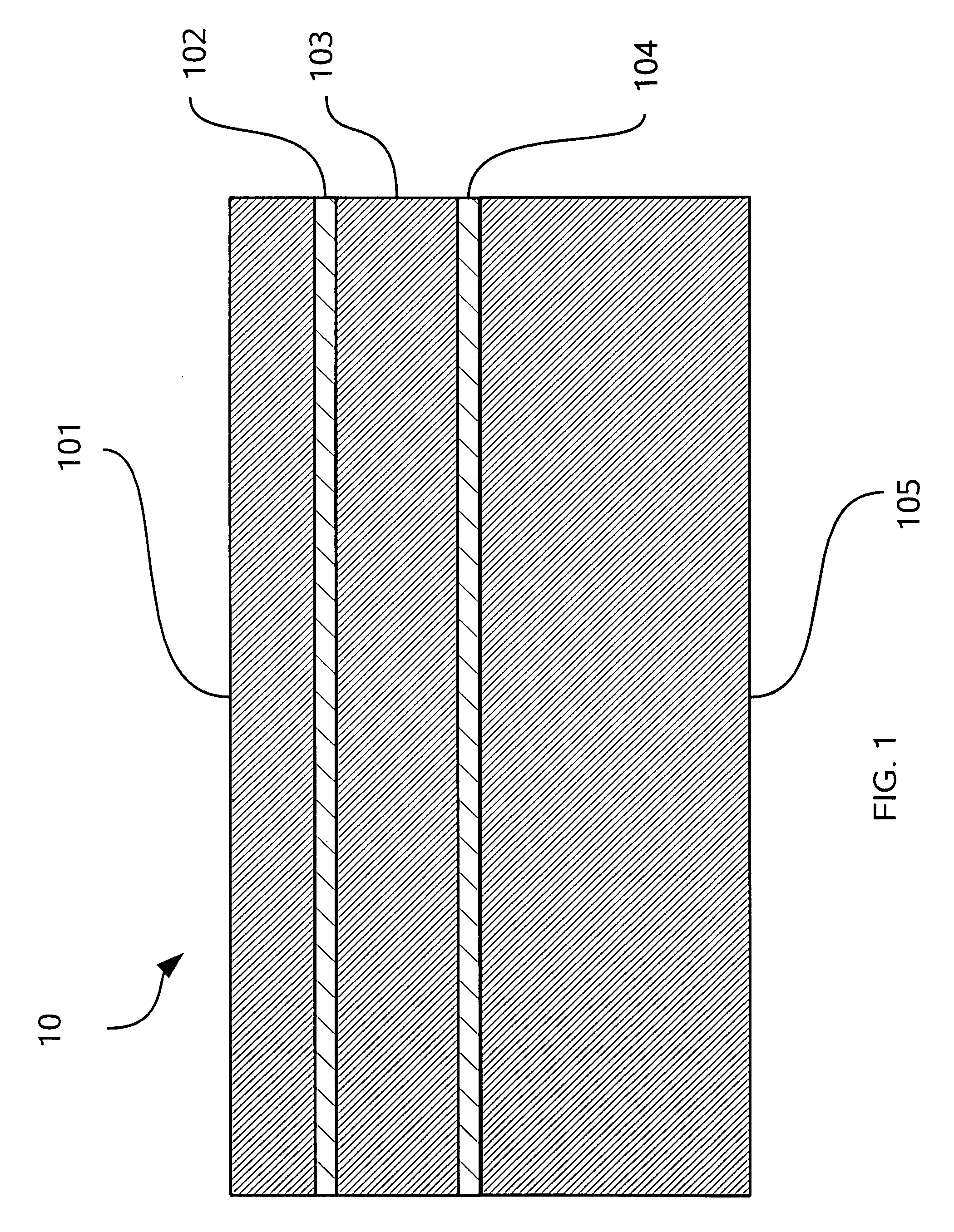
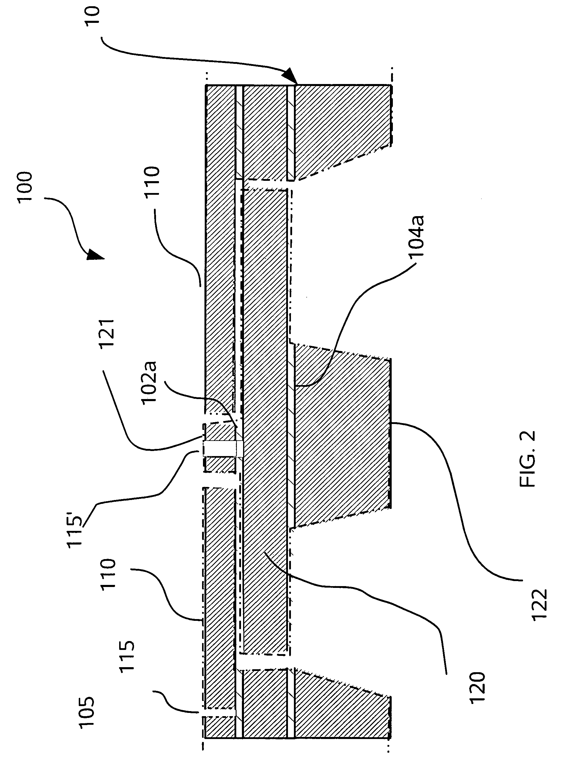
[0026]Referring to FIGS. 1 through 12, wherein like reference numerals refer to like components in the various views, there is illustrated therein a new and improved accelerometer, generally denominated 100 herein.

[0027]Accelerometers fabricated on semiconductor substrates such as silicon wafers are well known. They frequently deploy one or more static electrodes spaced apart from dynamic electrodes that move in response to acceleration. A silicon substrate from which the structure is fabricated is also etched in some manner to form a spring or hinge that allows the dynamic electrode to move. The change in capacitance between the static and dynamic electrodes, upon movement of the dynamic electrode, is used to quantify the magnitudes and direction of the movement. The dynamic electrode acts as the proof mass that increases its movement in response to the acceleration.

[0028]In accordance with the present invention, the accelerometer is preferably a MEMS device fabricated from a doubl...


PUM


Abstract

A 3-dimensional MEMS accelerometer fabricated on a single planar substrate deploys three co-planar sensor elements. Each sensor element is a capacitive device deploying a static electrode plate and a parallel dynamic electrode plate supported by a torsion beam. The dynamic electrode plate also includes a proof mass portion that displaces the center of gravity to below the plane of the plate. Two of the sensor elements are identical and rotated by 90 degrees on the planar substrate. The third capacitive sensor has two pairs of adjacent capacitive plates, each one having a dynamic electrode plate is suspended by a torsion beam. The proof mass on each dynamic electrode plates however is offset laterally from the torsion axis in opposite directions from the other plates to cancel the their respective capacitance charges induced by in-plane acceleration. However, this arrangement also adds the capacitive change induced by acceleration orthogonal to the planar substrate.

Description

CROSS REFERENCE TO RELATED APPLICATIONS[0001]The present application claims priority to the US provisional application for an “Accelerometer” having application Ser. No. 60 / 988,114, which was filed on Nov. 15, 2007, which is incorporated herein by referenceBACKGROUND OF INVENTION[0002]The present invention relates to micro-mechanical electrical systems (MEMS) type device for measuring vibration and movement, and more particularly to a MEMS accelerometer.[0003]MEMS type devices for use as sensors and accelerometers are well known. Such devices are generally fabricated on a silicon or related planar substrate by semi-conductor manufacturing type methods, such as the use of photo-resists, masks and various etching processes to fabricate a proximity sensor that includes a suspended proof mass member and means to measure the deflection of the proof mass suspending means. Such devices have inherent limitations on the minimum size, detection limit, sensitivity and the like, largely due to ...

Claims


Application Information

Patent Timeline
Patent Type & Authority Patents(United States)
IPC IPC(8): G01P3/04
CPCG01P15/0802G01P15/125G01P15/18G01P2015/0834G01P2015/0837G01P2015/0848
Inventor AXELROD, NOELOFEK, ERAN
Owner PHYSICAL LOGIC LTD
Why Eureka
Try Eureka