
Cutting insert

a cutting insert and insert technology, applied in the field of cutting inserts, can solve the problems of cutting inserts b>100/b> being damaged, machined surfaces might be damaged, and cutting inserts might be damaged, and achieve the effect of excellent chip discharge properties

Active Publication Date: 2012-03-20
KYOCERA CORP
View PDF30 Cites 16 Cited by
  • Summary
  • Abstract
  • Description
  • Claims
  • Application Information

AI Technical Summary

Benefits of technology

The design ensures stable and smooth chip discharge, reducing chip accumulation and damage, and maintaining tool integrity during long-term grooving operations, especially in internal turning where space is limited.

Problems solved by technology

Hence the remaining chips will remain between the cutting insert 100 and the work material, so that the machined surface might be damaged and the cutting insert 100 might be damaged.
As a result, the chips are caught by the cutting insert 100 and the holder, so that the machined surface might be damaged and the cutting insert 100 and the holder might be damaged.
Consequently, in the cutting inserts disclosed in Patent Documents 2 and 3, the chips riding on the ascending portion may be caught by the cutting insert and the holder, thus damaging the machined surface.Patent Document 1: Japanese Unexamined Utility Model Publication No. 64-56904Patent Document 2: Japanese Unexamined Patent Publication No. 2000-176708Patent Document 3: Japanese Unexamined Patent Publication No. 2006-150584

Method used


Image

  • Cutting insert
  • Cutting insert
  • Cutting insert

Examples


example 1

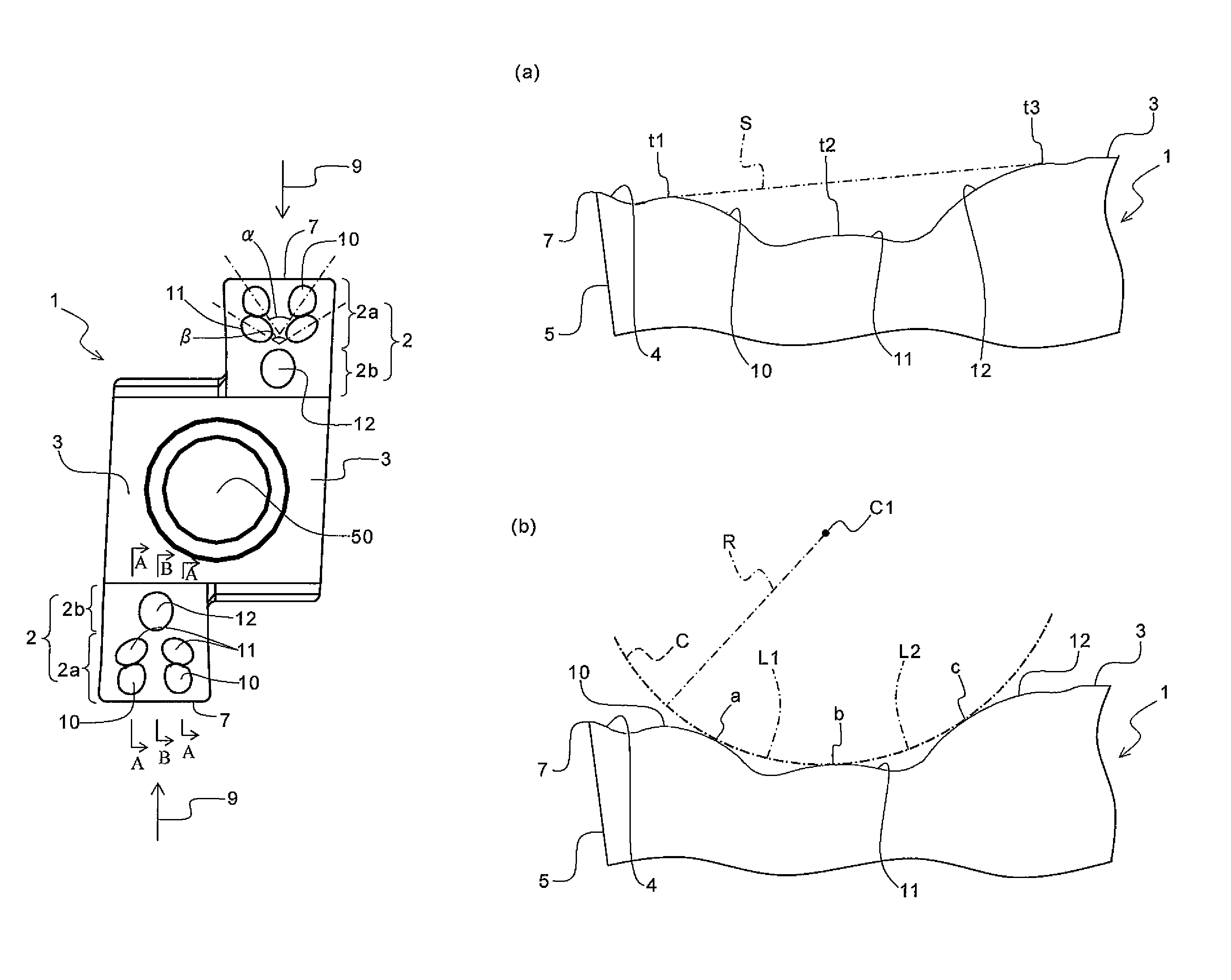
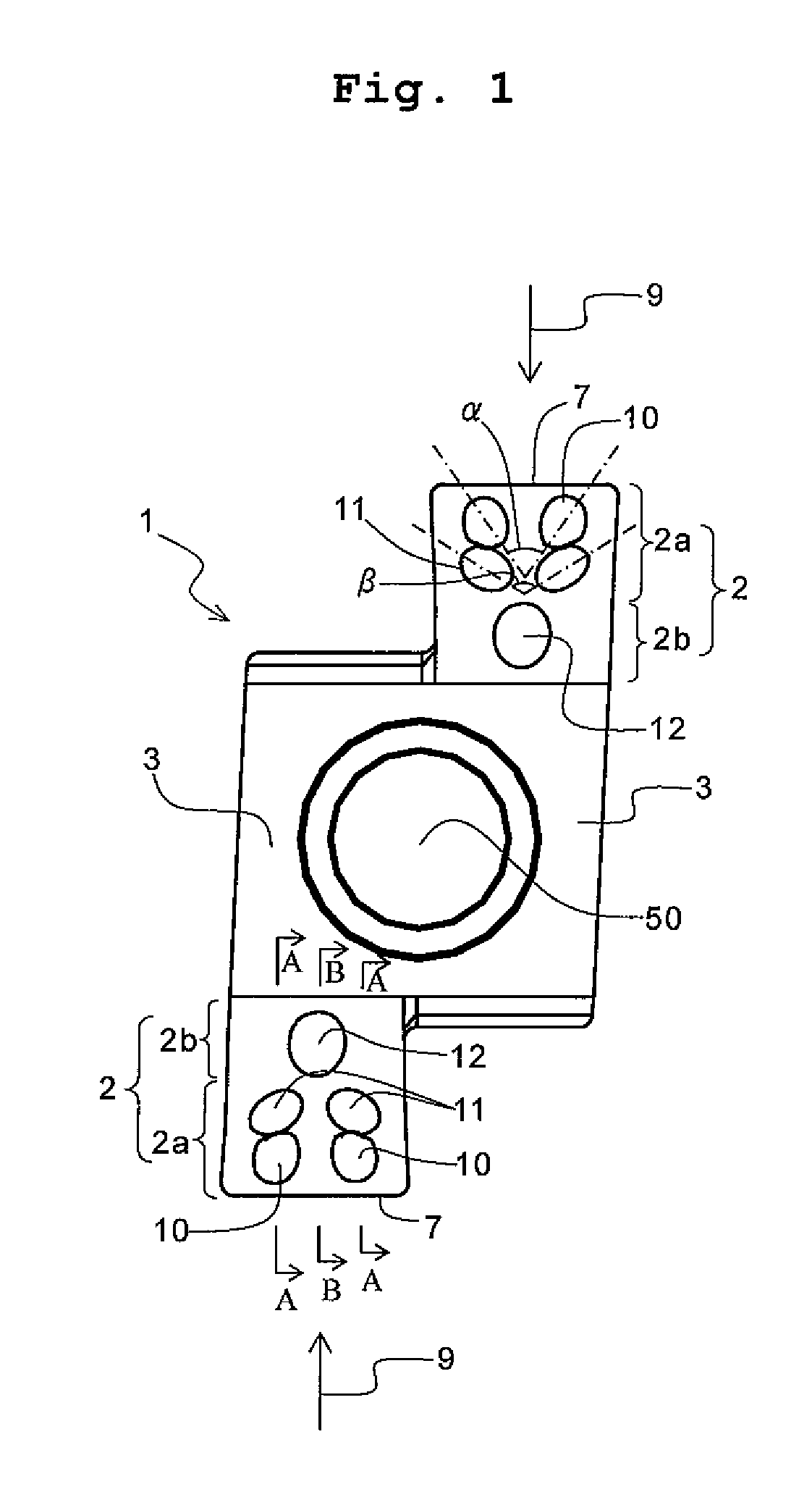
[0101]The insert 1 having the configuration shown in FIG. 1 as described above was manufactured. Specifically, the insert main body of the insert 1 was composed of coated cemented carbide having a hard thin film coated on the surface of a sintered cemented carbide body. The dimensions of the insert 1 are as follows. As the projection height, the thickness direction dimension from the boundary line between the projection and the rake face to the top portion of the projection (the dimension in the direction substantially perpendicular to the mounting surface of the holder) was measured in the section passing through the top portion of the projection and substantially parallel to the front cutting edge 7 and substantially perpendicular to the rake face. As the major axis length and minor axis length, the maximum dimensions perpendicular to an imaginary symmetrical axis in the plane view were measured, respectively. As the length of the flat surface 4, the dimension along a flat surface...

example 2

[0132]The insert 1 of Example 1 was used to evaluate the influence of the first projection 10 on the section of the chip 60. Specifically, as shown in FIG. 19, the evaluation was made by visually observing a plurality of sections of the generated chip 60. As a result, it was found that the section at a specific point had a characteristic sectional shape, and the sections at other points had a similar shape.

[0133]In FIG. 19, the point corresponding to the point having the similar sectional shape is plotted as Ia, and the specific point is plotted as Ib. The results thereof are shown in FIGS. 20(a) and (b). FIG. 20(a) shows the section of the chip 60 at the Ia in FIG. 19, and FIG. 20(b) shows the section of the chip 60 at the Ib in FIG. 19. The Ib having the characteristic sectional shape was 1 mm apart from the tip end of the chip 60.

[0134]As apparent from FIGS. 20(a) and (b), it can be seen that the section of the chip 60 is transformed from the section shown in FIG. 20(a) to the se...


PUM

PropertyMeasurementUnit
distanceaaaaaaaaaa
distancesaaaaaaaaaa
lengthaaaaaaaaaa

Abstract

A cutting insert includes a rake face region located on an upper surface, a flank located on a front surface, and a cutting edge located at an intersection between the rake face region and the flank. At least three types of projections having different distances from the cutting edge are on the rake face region. When these three types of projections are arranged in the order of increasing distance from the cutting edge, namely, a first projection, a second projection and a third projection, the top of the second projection is lower than an imaginary straight line connecting the top of the first projection and the top of the third projection in the side view.

Description

CROSS-REFERENCE TO THE RELATED APPLICATIONS[0001]This application is a national stage of international application No. PCT / JP2007 / 067040 filed Aug. 31, 2007, which also claims the benefit of priority under 35 USC 119 to Japanese Patent Application No. 2006-296614 filed on Oct. 31, 2006, the entire contents of which are incorporated herein by reference.[0002]The present invention relates to a cutting insert used for grooving in the turning process of metal materials and the like.BACKGROUND ART[0003]The cutting insert for grooving is required to permit a smooth discharge of chips generated. In order to improve the chip discharge property, various considerations have been conventionally given to the shape of the rake face of the cutting insert (for example, refer to Patent Document 1).[0004]FIG. 21 is a partially enlarged schematic perspective view showing the neighborhood of one end of the related art cutting insert as described in the patent document 1. As shown in FIG. 21, a cutting...

Claims


Application Information

Patent Timeline
Patent Type & Authority Patents(United States)
IPC IPC(8): B23B27/22B23B27/04
CPCB23B27/007B23B27/045B23B27/16B23B2200/321B23B2200/3627B23B2220/12Y10T82/10Y10T407/2268Y10T407/235Y10T407/25Y10T407/2274Y10T407/245Y10T407/24B23B2270/16
Inventor UCHIJO, KENJIINOUE, YOSHIHIRO
Owner KYOCERA CORP
Learn More