Insert for drill

a drill bit and insert technology, applied in the field of drill bit inserts, can solve the problems of clinging to the holder, the outer cutting edge generated by the cutting edge under high rotational speed is unsusceptible, and the spiral three-dimensional shape of the chip, so as to achieve the effect of wide chip discharge space and smooth discharg

Active Publication Date: 2011-07-07
KYOCERA CORP
View PDF6 Cites 9 Cited by
  • Summary
  • Abstract
  • Description
  • Claims
  • Application Information

AI Technical Summary

Benefits of technology

[0012]An aspect of the present invention is to provide a drill insert having excellent chip discharge performance.
[0020]According to the drill insert, the drill, and the cutting method, it is capable of suitably curling and cutting the chips generated by the first cutting edge (the outer cutting edge). It is also capable of ensuring a wide discharge space of the chips generated by the second cutting edge (the inner cutting edge). Consequently, the chips generated by any one of the first cutting edge and the second cutting edge can be smoothly discharged.

Problems solved by technology

That is, the chips generated by the inner cutting edge have a spiral three-dimensionally complicated shape.
Particularly, when machining a work material having excellent ductility, such as stainless steels or low carbon steels, the chips generated by the outer cutting edge under high rotational speed are unsusceptible to curling, so that they are likely to extend without being cut and likely to cling to the holder during the machining.
There has been the problem that these chips cannot be smoothly discharged through the breaker grooves.
However, there has been the problem that merely increasing the height of the raised part increases the level difference between the raised part and the upper face along the inner cutting edge, thereby making it easy for the chips to accumulate at the level difference portion.
Particularly, there has been a noticeable problem that the chips having a three-dimensionally complicated shape generated by the inner cutting edge accumulate at the level difference portion of the inner cutting edge located at the outer periphery side of the inner cutting edge which corresponds to a discharge direction in which the chips generated by the inner cutting edge are discharged outside of the holder.
That is, there has been the problem that a further increase in the height of the raised part for improving the discharge performance of the chips generated by the outer cutting edge contributes to improving the discharge performance of the chips generated by the outer cutting edge, while deteriorating the discharge performance of the chips having the three-dimensionally complicated shape generated by the inner cutting edge.

Method used


Image

  • Insert for drill
  • Insert for drill
  • Insert for drill

Examples


first embodiment

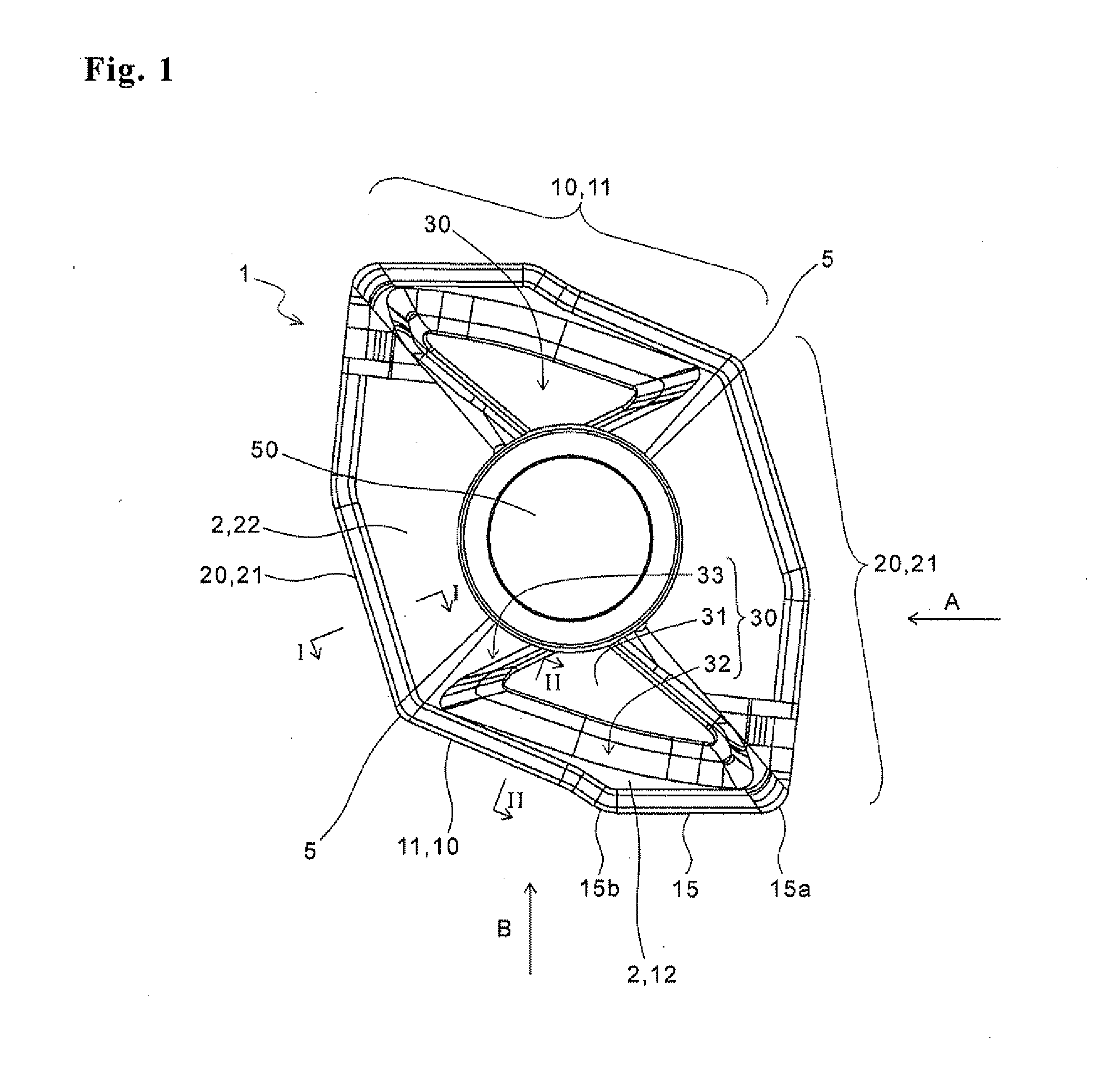
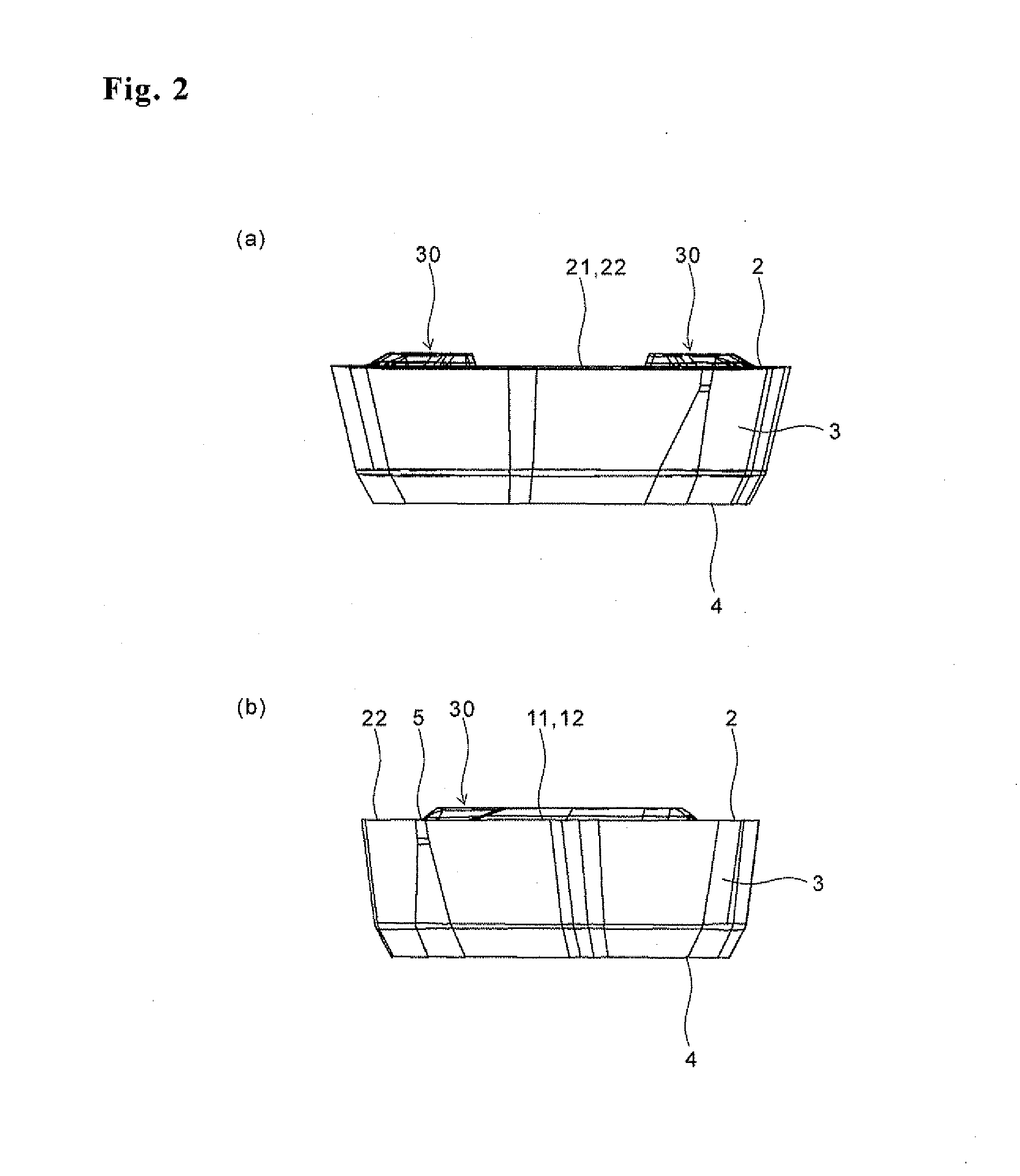
[0034]A first embodiment of the drill insert according to the present invention is described below in detail with reference to FIG. 1 to FIG. 5(d). As shown in FIG. 1, an insert 1 according to the present embodiment has a substantially polygonal plate shape when viewed from above. The insert 1 is constructed from one in which a film is coated onto a sintered body such as cemented carbide, cermet, ceramics, or the like. The film is for improving the wear resistance of the insert 1. As the composition thereof, there are for example titanium based compounds such as titanium carbide, titanium nitride, and titanium carbon nitride, alumina, or the like. The film may be made of at least one layer or alternately, a plurality of layers. The insert 1 is not limited to these film-coated ones, and those constructed from the sintered body without a film coated thereon may be used.

[0035]The insert 1 includes an upper face 2. A through hole 50 is formed at a mid-portion of the upper face 2. The th...

third embodiment

[0064]In the insert according to a third embodiment, an upper face 2 has a predetermined second raised part in addition to a first raised part 30. The insert according to the present embodiment is described below in details with reference to FIGS. 7(a) and 7(b). In FIGS. 7(a) and 7(b), similar reference numerals are used to denote the components similar to those in FIGS. 1 to 6(b) described above, and the descriptions thereof are omitted.

[0065]As shown in FIG. 7(a), the insert 45 according to the present embodiment includes the second raised part 46 in a second region 22. The second raised part 46 is disposed to lie at a lower position than the first raised part 30. Specifically, an upper portion 47 of the second raised part 46 is located at a lower position than an upper portion 31 of the first raised part 30. As shown in FIG. 7(b), the second raised part 46 has the upper portion 47, and a breaker portion 48 inclined from the upper portion 47 so as to lie at a lower position toward...

second embodiment

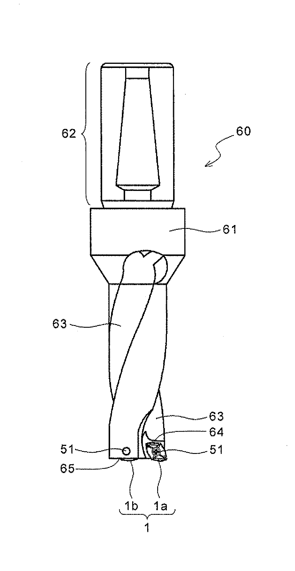
[0082]In the drill according to a second embodiment, both of first and second insert pockets have an axial rake. The drill according to the present embodiment is described below in details with reference to FIGS. 11 and 12 by taking, for example, the case of attaching the insert 1 according to the first embodiment. The inserts indicated by the dash-double dot lines in FIGS. 12(a) and 12(b) show the states of the insert units before being attached to the insert pockets. In FIGS. 11 and 12, similar reference numerals are used to denote the components similar to those in FIGS. 1 to 10 described above, and the descriptions thereof are omitted.

[0083]As shown in FIG. 11, in the drill 70 according to the present embodiment, the axial rake θ1 of a second insert pocket 75 is larger than the axial rake θ2 of a first insert pocket 74, and both of the axial rakes θ1 and θ2 are positive. Thereby, when the inner insert 1b is attached to the second insert pocket 75, as shown in FIG. 12(a), a secon...


PUM

PropertyMeasurementUnit
angleaaaaaaaaaa
widthaaaaaaaaaa
angleaaaaaaaaaa

Abstract

A drill insert of the present invention comprises a corner part, and an upper face having a first side and a second side disposed on both sides of the corner part, respectively. The drill insert comprises a first cutting edge formed along the first side; a second cutting edge formed along the second side; a first region of the upper face located along the first cutting edge;a second region of the upper face located along the second cutting edge; and a first raised part disposed in the first region so as to lie at a higher position than the second region. The first raised part has an upper portion; a breaker portion configured to be inclined so as to become at a lower position as the first raised part extends from the upper portion; and a side portion configured to be inclined so as to become at a lower position as the side portion extends from the upper portion. The first raised part is disposed at a position closer to the first cutting edge than a bisector of the corner part when viewed from above.

Description

TECHNICAL FIELD[0001]The present invention relates to a drill insert having excellent chip discharge performance.BACKGROUND ART[0002]As a drill for drilling holes, there are for example those in which an inner insert and an outer insert are detachably attached to the tip end of a holder so that their respective rotation loci are partially overlapped with each other. Among others, those in which the inner insert and the outer insert have the same shape are frequently used. That is, the drill in which one type of drill insert (hereinafter referred to as “insert” in some cases) is detachably attached to each of the inner side and the outer side at the tip end of the holder is frequently used.[0003]The inserts used for this drill include an inner cutting edge and an outer cutting edge. The inner cutting edge is the cutting edge for mainly cutting (machining) an inner portion of a bottom face of a hole when it is used as the inner insert. The outer cutting edge is the cutting edge for ma...

Claims


Application Information

Patent Timeline
Patent Type & Authority Applications(United States)
IPC IPC(8): B23B51/00B23B27/16B23B35/00
CPCB23B27/143B23B51/048Y10T408/9098Y10T408/04Y10T408/89B23B2200/321Y10T408/87Y10T408/905Y10T407/23Y10T408/03B23B51/00
Inventor OKUMURA, TAKASHI
Owner KYOCERA CORP
Why Eureka
Try Eureka