

Cutting insert, cutting tool, and method of manufacturing machined product using the same
a cutting tool and cutting insert technology, applied in the direction of manufacturing tools, shaping cutters, transportation and packaging, etc., can solve the problems of finely divided chips that cannot be smoothly discharged, cutting inserts, holder, or machined surfaces, etc., to reduce lateral vibration of chips, improve chip stiffness, and reduce cutting resistance
- Summary
- Abstract
- Description
- Claims
- Application Information
AI Technical Summary
Benefits of technology
Problems solved by technology
Method used
Image

Examples
fourth embodiment
[0104]An insert according to a fourth embodiment of the present invention is described in detail with reference to FIGS. 13 to 18. In FIGS. 13 to 18, the same components as the foregoing FIGS. 1 to 12 are identified by the same reference numerals, and the description thereof is omitted here.
[0105]As shown in FIGS. 13 and 14, the insert 51 of the present embodiment includes a body having an upper surface 52, a lower surface 53, and a side surface 54. In the present embodiment, the body has a rectangular shape having four long sides of equal length and four corners.
[0106]The insert 51 is a so-called positive type insert in which a cutting edge 55 is located at an intersection region of the upper surface 52 and the side surface 54, and a positive clearance angle θ3 is applied to the side surface 54, as shown in FIGS. 15 and 16. In the present embodiment, the clearance angle θ3 is constant in a region along the cutting edge 55.
[0107]A concave part 56 is located on at least one surface o...
first embodiment
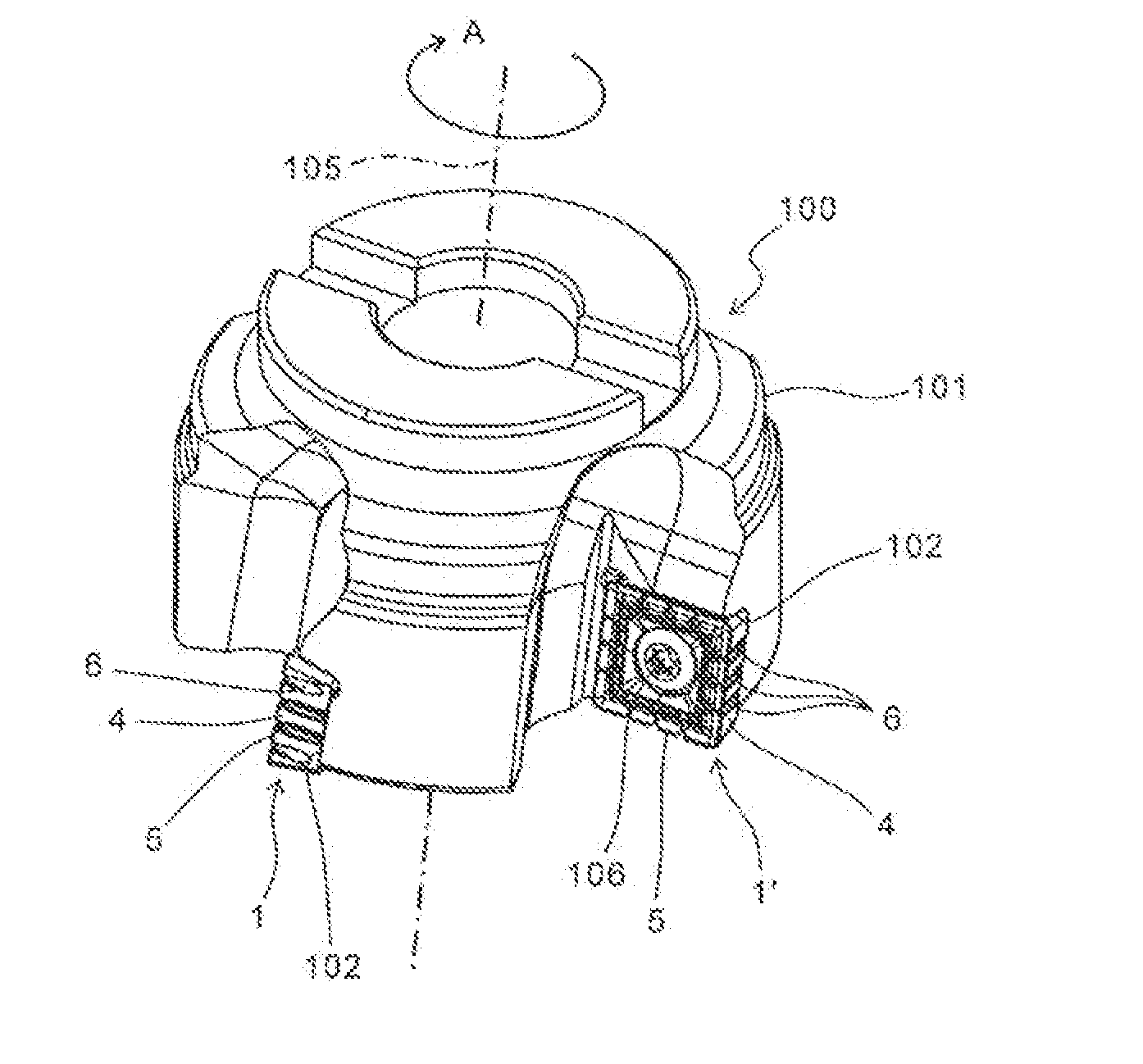
[0125]Next, a cutting tool according to a first embodiment of the present invention is described in detail with reference to FIG. 19.
[0126]As shown in FIG. 19, the cutting tool 100 of the present embodiment is a face milling cutter, and includes the cutting insert 1 according to the foregoing first embodiment, and a holder 101 configured to attach the insert 1 to a front end thereof.
[0127]In the cutting tool 100, the insert 1′ is also attached to the holder 101, in addition to the insert 1. In the insert 1′, the three concave parts 6 are formed on the side surface 4. The shape of the individual concave parts 6 is identical to the shape of the second concave part 62 having the other end 62a on the lower surface 3 as described in the insert 1. Other configurations are similar to those of the insert1.
[0128]On the other hand, the holder 101 has a rotor shape around a central axis 105, and has a plurality of insert pockets 102. The individual insert pockets 102 are formed at predetermine...
second embodiment
[0132]Next, a cutting tool according to a second embodiment of the present invention is described in detail.
[0133]The cutting tool of the present embodiment uses the holder 101 of the cutting tool 100 according to the foregoing first embodiment. In the cutting tool of the present embodiment, the inserts 31 and 31′ according to the foregoing second and third embodiments are attached to a plurality of insert pockets 102 located in the holder 101.
[0134]A plurality of inserts 31 and 31′ are attached so that the cutting edges 35 protrude outward from an outer peripheral surface of the holder 101. At this time, all of the plurality of inserts 31 and 31′ are attached so that the divided cutting edges protrude from the insert pockets 102, and the concave parts of certain inserts 31 and inserts 31′ correspond to the divided cutting edges of the inserts 31 and 31′ adjacent thereto.
[0135]That is, in the inserts 31 and 31′ located behind in a rotation direction of the holder 101, the divided cu...
PUM
| Property | Measurement | Unit |
|---|---|---|
| rake angle θ1 | aaaaa | aaaaa |
| rake angle θ1 | aaaaa | aaaaa |
| clearance angle | aaaaa | aaaaa |
Abstract
Description
Claims
Application Information