Conductor connection structure

a connection structure and conductor technology, applied in the direction of coupling contact members, coupling device connections, contact members penetrating/cutting insulation/cable strands, etc., can solve the problem of increasing difficulty in size reduction, and the size of the connecting portion. problem, to achieve the effect of reducing the number of parts, reducing the size of the connection portion, and reducing production costs

Inactive Publication Date: 2012-03-20
HITACHI CABLE
View PDF19 Cites 8 Cited by
  • Summary
  • Abstract
  • Description
  • Claims
  • Application Information

AI Technical Summary

Benefits of technology

[0012]Accordingly, it is an object of the present invention to provide a conductor connection structure, which obviates the above problems, thereby ensuring reduction in the size of its portion connecting conductors together, and in the number of parts, and inhibiting wear in the contact portion of the conductors caused by terminal insertion / removal.
[0046]In one embodiment of the invention, a stranded conductor of cable is converted into a terminal to form a female terminal cable, so that no conventional terminal used is required, and the connection portion of the conductors (the connection portion of the female terminal and male terminal member) can therefore be smaller than the outside diameter of the cable, thus ensuring the size reduction of the connection portion. Also, because of no terminal required, it can be ensured that the number of parts is reduced, thereby allowing a reduction in production cost. Further, reduction in the size and the number of parts can ensure the weight reduction of the conductor connection structure. Also, because of no terminal required, the increase of the connection resistance caused in the connection portion of the stranded conductor and the terminal, and therefore heat generation in the connection portion can be inhibited. Further, a slidable fastening member may be provided around the perimeter of the female terminal to tighten the female terminal only when connected to the male terminal member, so that the wear in the contact portion caused by the insertion / removal of the male terminal member can be inhibited, and the male terminal can securely be fixed into the female terminal. This can realize the conductor connection structure whose connection portion is not adversely affected by vibration, and whose contact portion is not worn during insertion / removal. Thus, this conductor connection structure is suitable for conductor connection structure for electric cables used in vibrational environments, such as vehicles.

Problems solved by technology

With the conventional terminal connection type conductor connection structures, however, there is the problem that the mating male and female terminal portion tends to be larger than the outside diameter of the cables.
This increases the size of the connecting portion, to cause difficulty in size reduction of, especially, the portion connecting plural cables to other cables (or pin terminals).
Further, there is the problem of the increasing number of parts due to requirements for connecting the terminals to the conductors of the cables, respectively.
However, there is the problem that the vibration-resistant spring accelerates wear in the contact portion caused by terminal insertion / removal.

Method used


Image

  • Conductor connection structure
  • Conductor connection structure
  • Conductor connection structure

Examples


first embodiment

[0091]Below is described a conductor connection structure in the first embodiment according to the invention, referring to FIGS. 1A-1F, 2A-2C, 3A, 3B, 4A, 4B, 5A and 5B.

[0092]A conductor connection structure of the invention is for connecting a cable to a male terminal member (another cable or a pin terminal), and is used in, for example, large-current wire harness connectors for use in hybrid vehicles, electric vehicles, and the like.

[0093]Female Terminal Cable 1

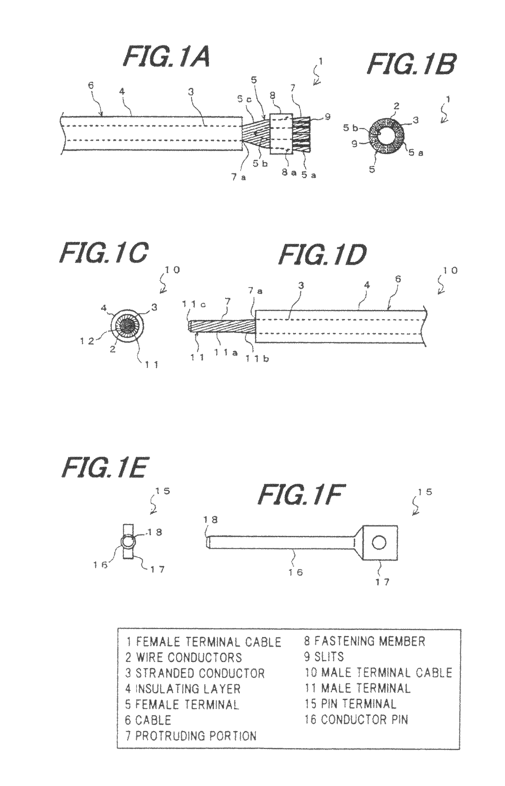
[0094]FIG. 1A is a front view showing a female terminal cable used in the conductor connection structure of the first embodiment. FIG. 1B is a side end face view showing the female terminal cable of FIG. 1A.

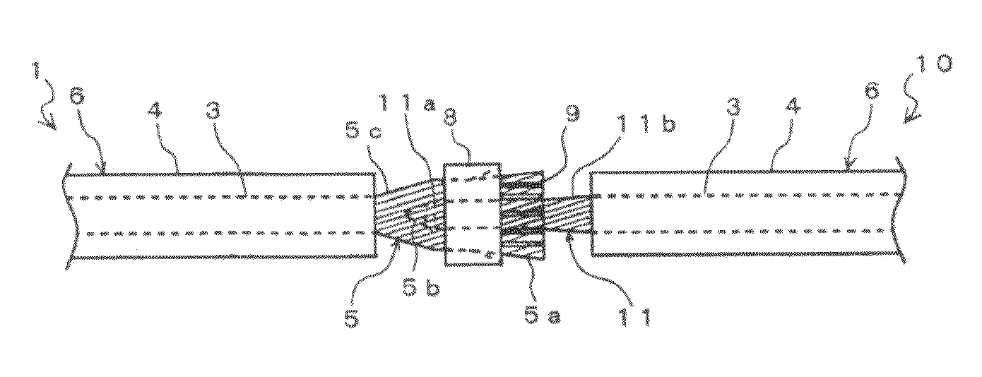
[0095]As shown in FIGS. 1A and 1B, a female terminal cable 1 comprises a cable 6, a female terminal 5 formed integrally with an end of the cable 6, and a fastening member (spring) 8 provided slidably around the perimeter of the female terminal 5.

[0096]Cable 6

[0097]The cable 6 comprises a stranded conductor 3 comprising t...

second embodiment

[0141]Referring to FIG. 6, a female terminal cable 61 is formed with a stopper 62 at the end of the cylindrical portion 5a of the female terminal 5 for preventing the fastening member 8 from slipping, in the female terminal cable 1 of FIGS. 1A and 1B. The stopper 62 is provided to protrude diametrically outward from the end of the cylindrical portion 5a.

[0142]The stopper 62 may be formed by bending a portion of the end of the cylindrical portion 5a when widening the end of the cylindrical portion 5a into the wide-end shape after or simultaneously with the pressure molding of the female terminal 5.

[0143]Although FIG. 6 shows the stopper 62 formed at the portion of the end of the cylindrical portion 5a, the stopper 62 may be formed around the entire perimeter of the end of cylindrical portion 5a.

[0144]The stopper 62 can prevent the fastening member 8 from accidentally slipping out from the female terminal 5 when sliding the fastening member 8 during the fastening.

[0145]Although the ...

third embodiment

[0146]Although in the above embodiments the thickness of the stranded conductor 3 in the cylindrical portion 5a of the female terminal 5 is constant, the thickness of the stranded conductor 3 in the cylindrical portion 5a of the female terminal 5 may be formed in a tapered shape, which is widened toward the end of the cylindrical portion 5a, as shown in FIG. 7. Namely, the cylindrical portion 5a of the female terminal 5 may be formed in a tapered shape, so that the thickness d2 of the end of the cylindrical portion 5a is greater than the tapered base 5c-side thickness dl of the cylindrical portion 5a.

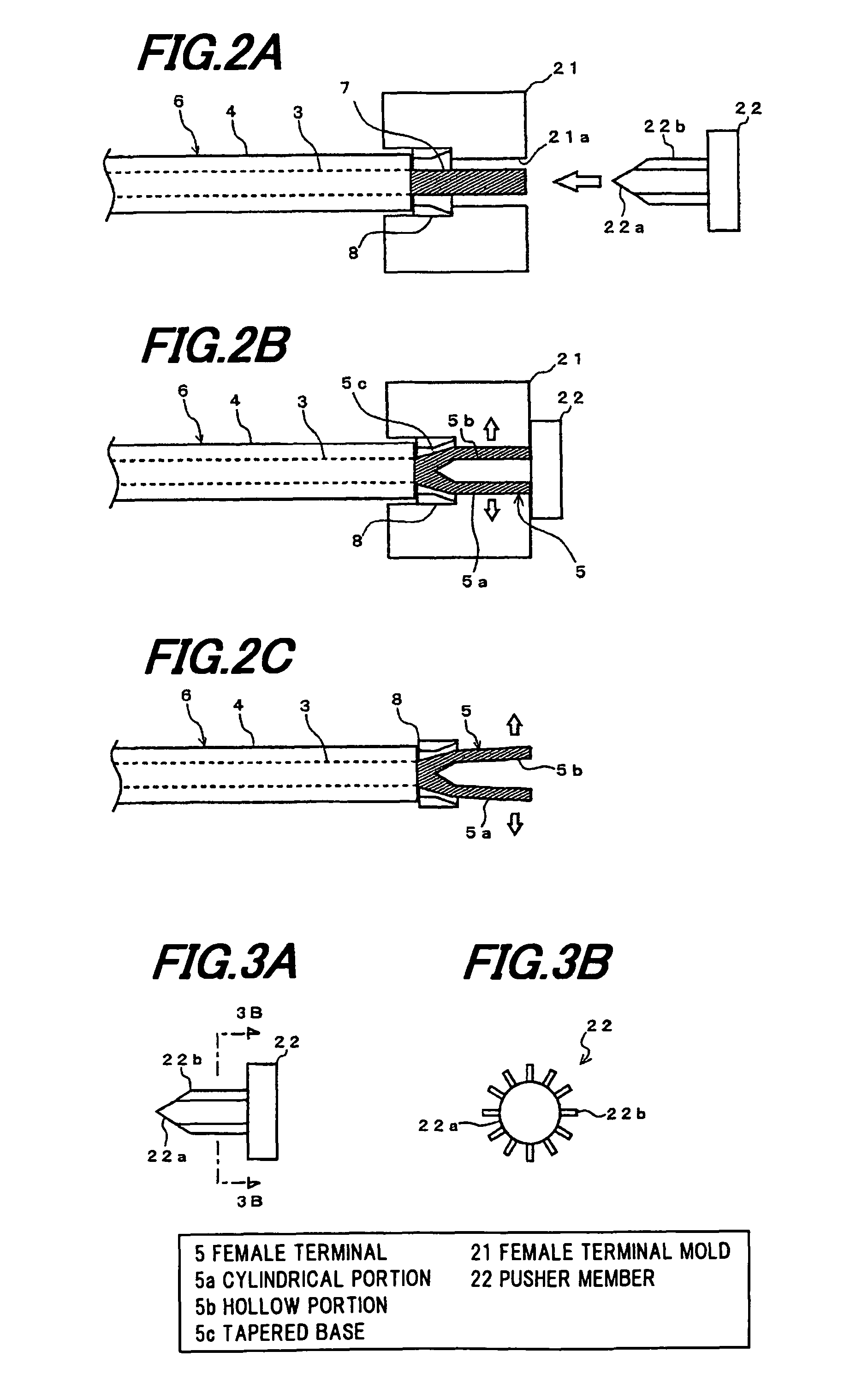
[0147]In this case, forming the diameter of hollow portion 5b slightly greater than the outside diameter of the terminal portion 11a of the male terminal 11 can inhibit wear in the contact portion caused by the insertion / removal of the male terminal member. When forming a female terminal cable 71 in FIG. 7, a female terminal mold with a female terminal mold hole formed in a tapered sha...


PUM


Abstract

A conductor connection structure includes a cable including a stranded conductor composed of twisted plural wire conductors, and an insulating layer formed around the perimeter of the stranded conductor, the cable being connected to a male terminal member; a female terminal including a protruding portion formed by causing the stranded conductor to protrude from the insulating layer at an end of the cable, the female terminal being formed in a cylindrical shape by widening the center of an end of the protruding portion to make the protruding portion hollow, to insert the male terminal member into the protruding portion; and a fastening member slidably provided around the perimeter of the female terminal, to tighten the female terminal when connected to the male terminal member, to fasten the male terminal member.

Description

[0001]The present application is based on Japanese patent application Nos. 2009-044269 and 2009-044270 filed on Feb. 26, 2009, the entire contents of which are incorporated herein by reference.BACKGROUND OF THE INVENTION[0002]1. Field of the Invention[0003]The present invention relates to a conductor connection structure, which is specially designed to be used in hybrid vehicles, electric vehicles, and the like.[0004]2. Description of the Related Art[0005]Conventionally, as a conductor connection structure for electrically connecting cable (insulated cable) conductors together, there is known a terminal connection type conductor connection structure which mates male and female terminals provided at ends of one cable and the other, respectively, to thereby electrically connect their respective conductors together.[0006]Also, as a conductor connection structure used in joints of large-capacity cables such as power cables (power electric cables), there is known a terminal connection ty...

Claims


Application Information

Patent Timeline
Patent Type & Authority Patents(United States)
IPC IPC(8): H01R4/50
CPCH01R4/5033H01R43/28H01R9/03Y10S439/93
Inventor TAKEHARA, HIDEAKI
Owner HITACHI CABLE
Why Eureka
Try Eureka