
System and method for spatial compounding using phased arrays

a phased array and spatial compounding technology, applied in the field of ultrasound imaging, can solve the problems of large amount of computation, large table size, and complex spatial compounding for phased arrays

Active Publication Date: 2012-03-20
FUJIFILM SONOSITE
View PDF5 Cites 20 Cited by
  • Summary
  • Abstract
  • Description
  • Claims
  • Application Information

AI Technical Summary

Benefits of technology

Simplifies spatial compounding calculations for phased arrays, reducing computational requirements and enabling efficient image formation with improved image quality and reduced artifacts.

Problems solved by technology

In general, spatial compounding for phased arrays is much more complicated because the beams are typically not equally spaced.
Therefore, a very large amount of computation and / or very large tables are required to register the image data from the different views.

Method used


Image

  • System and method for spatial compounding using phased arrays
  • System and method for spatial compounding using phased arrays
  • System and method for spatial compounding using phased arrays

Examples


Embodiment Construction

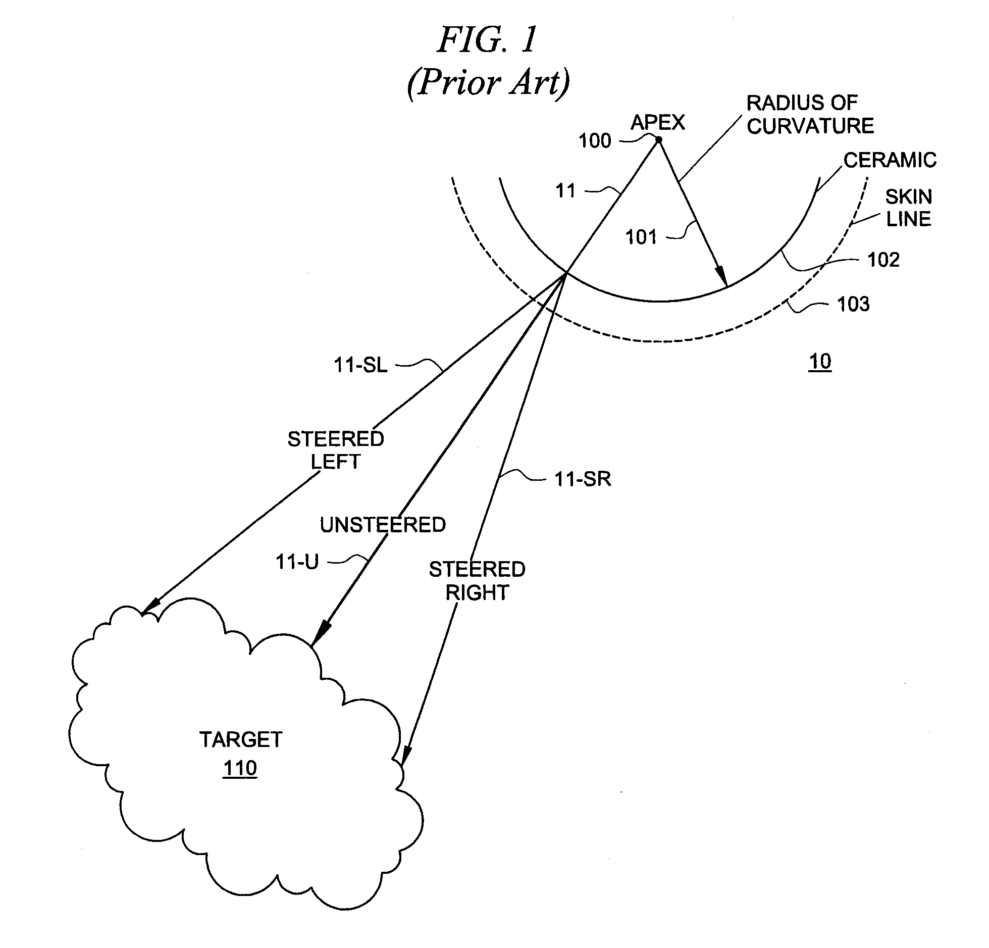
[0016]FIG. 1 shows one schematic illustration 10 of an embodiment of a the operational theory of image generation using a curved array in accordance with the prior art. FIG. 1 shows one method for spatially compounding beams formed along a curved array. This technique is well-known in the art and can be accomplished, for example, using concepts discussed in the above-identified U.S. patent application Ser. No. 11 / 749,319.

[0017]Curved array 102 has apex 100 and radius of curvature 101. Unsteered ray 11, emanating from apex 100 is perpendicular to the array surface, which in one embodiment can be ceramic. This ray (also called a beam) is steered left (11SL) and steered right (11SR) as discussed in the P35 application to paint the target, such as target 110 below skin line 103 of the subject. This trio of beams (as well as many others as are desired) can be moved anywhere along aperture 102 to form the different look directions that need to be acquired for spatial compounding.

[0018]The...


PUM


Abstract

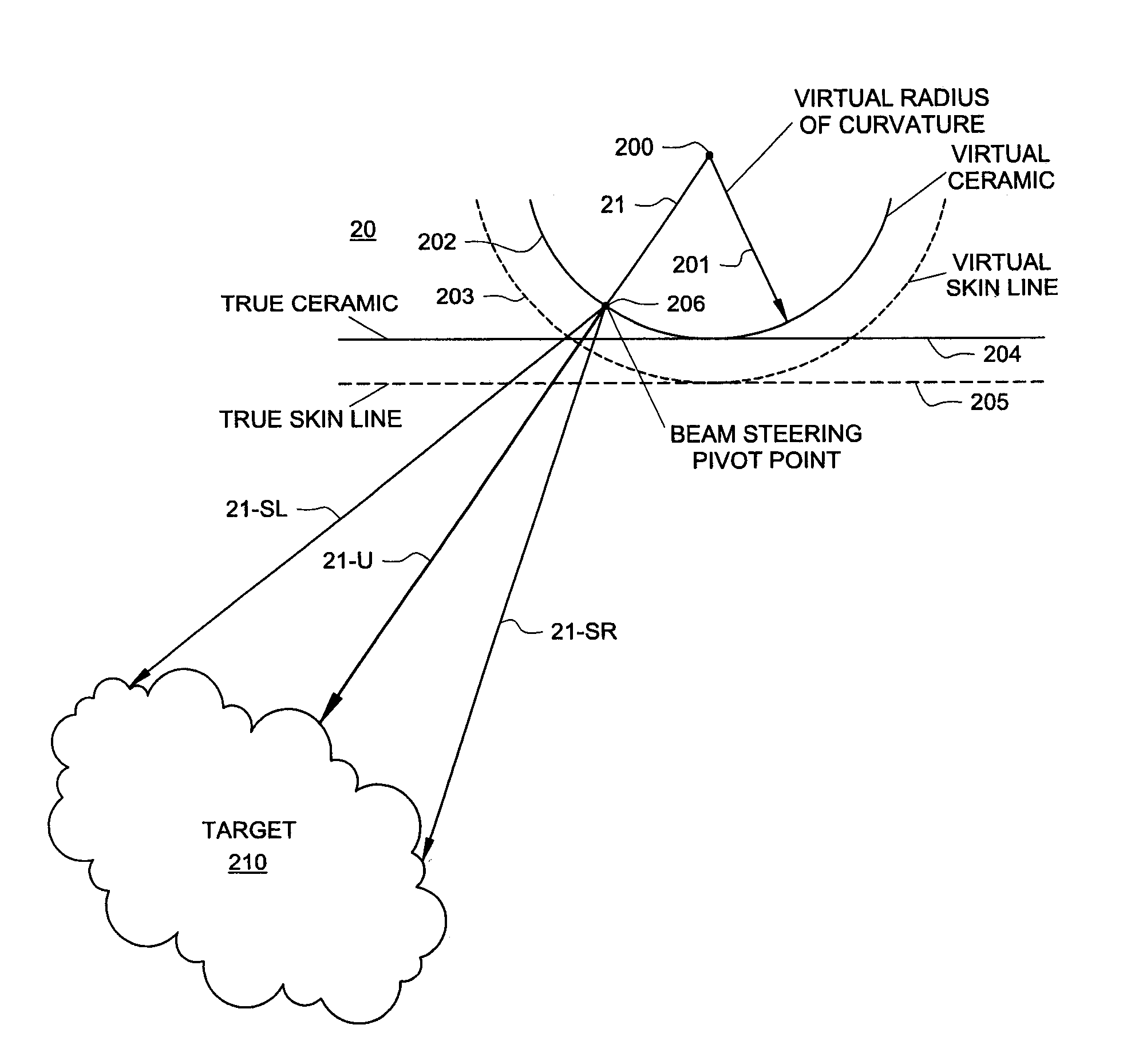
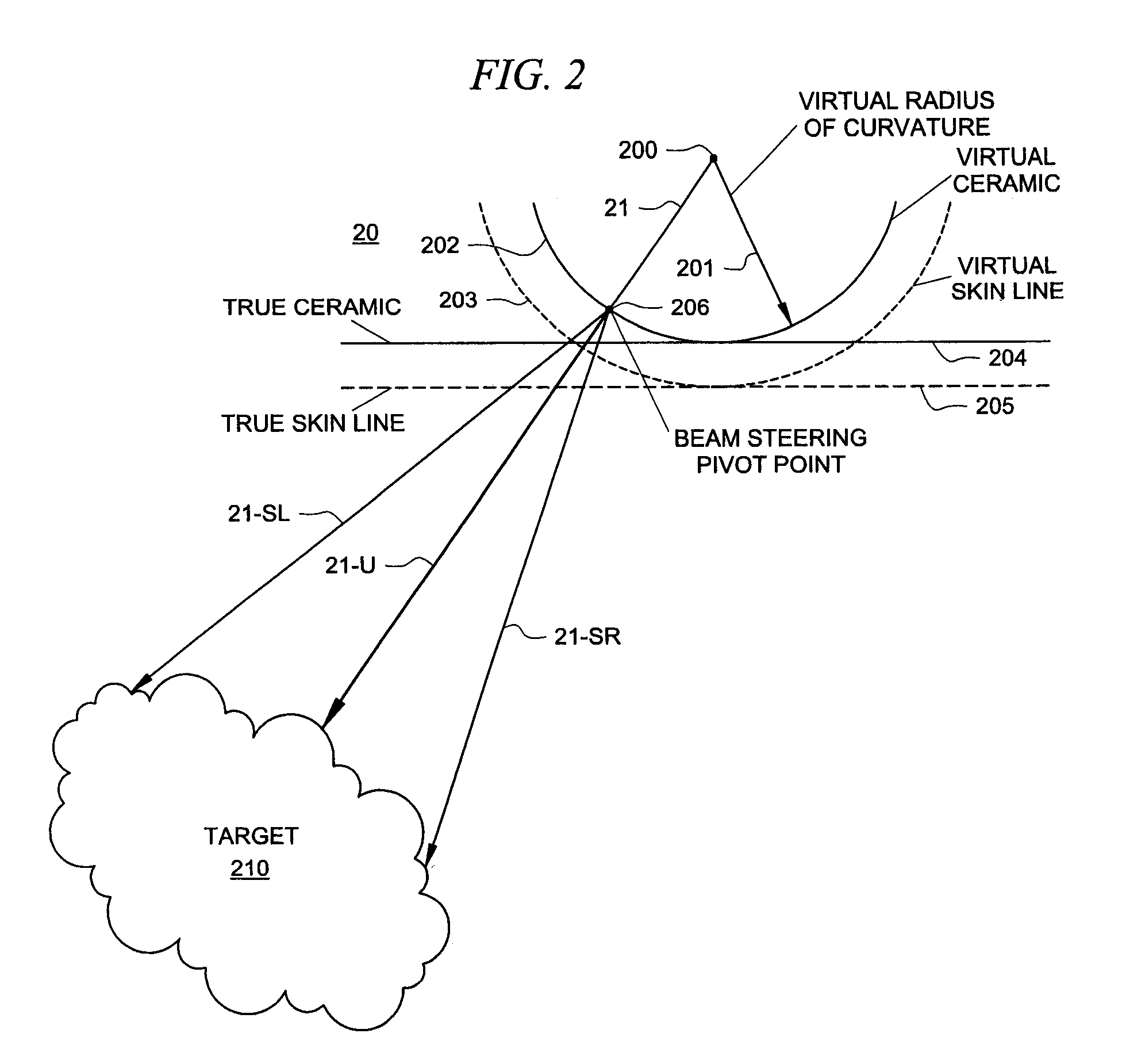
The present invention is directed to a system and method which makes a phased array look like a curved array for purposes of performing spatial compounding calculations. In one embodiment, the phased array is treated as though it were a curved array by creating both a virtual apex and a virtual radius of curvature. Based on this transformation, standard spatial-compounding resampling tables can be used just as they are with curved arrays. In one embodiment, after the data is compounded to form the target image, certain data is removed prior to the actual display. This removed data represents data generated by virtual rays the prior to the physical skin line of the phased array.

Description

CROSS-REFERENCE TO RELATED APPLICATIONS[0001]The present application is related to U.S. patent application Ser. No. 11 / 749,319 filed May 16, 2007 entitled “SYSTEM AND METHOD FOR OPTIMIZED SPATIO-TEMPORAL SAMPLING,” the disclosure of which is incorporated by reference herein.TECHNICAL FIELD[0002]This disclosure relates to ultrasound imaging and more particularly to systems and methods for spatial compounding using linear arrays and even more specifically to phased arrays.BACKGROUND OF THE INVENTION[0003]Spatial compounding is a method of creating an ultrasound image by compiling multiple views acquired at different angles. Each view is obtained from multiple lines of sight at different angles. This is a departure from traditional ultrasound imaging that used a single line of sight perpendicular to the scanhead face. The views from the multiple angles are combined to create a single image, thereby reinforcing real-tissue information and suppressing random artifacts. Spatial compoundin...

Claims


Application Information

Patent Timeline
Patent Type & Authority Patents(United States)
IPC IPC(8): A61B8/00
CPCA61B8/08A61B8/54G01S15/8995G01S15/8909G01S7/52085
Inventor LUNDBERG, ANDREW K.KAPLAN, MITCHELLSTONE, ROBERT E.PAILOOR, RAMACHANDRASIEDENBURG, CLINTON T.MAO, ZUHUA
Owner FUJIFILM SONOSITE
Learn More