
Disk drive device having airtight structure with improved airtightness

a disk drive and airtight structure technology, applied in the direction of casings/cabinets/drawers, instruments, casings/cabinets/drawers, etc., can solve the problems of increasing manufacturing costs, physical damage to the recording disk or the magnetic head, and unstable airtight performance in the through hole portion, so as to achieve the effect of stabilizing the airtightness of the disk drive devi

Inactive Publication Date: 2012-03-20
SAMSUNG ELECTRO MECHANICS JAPAN ADVANCED TECHNOLOGY CO LTD
View PDF20 Cites 6 Cited by
  • Summary
  • Abstract
  • Description
  • Claims
  • Application Information

AI Technical Summary

Benefits of technology

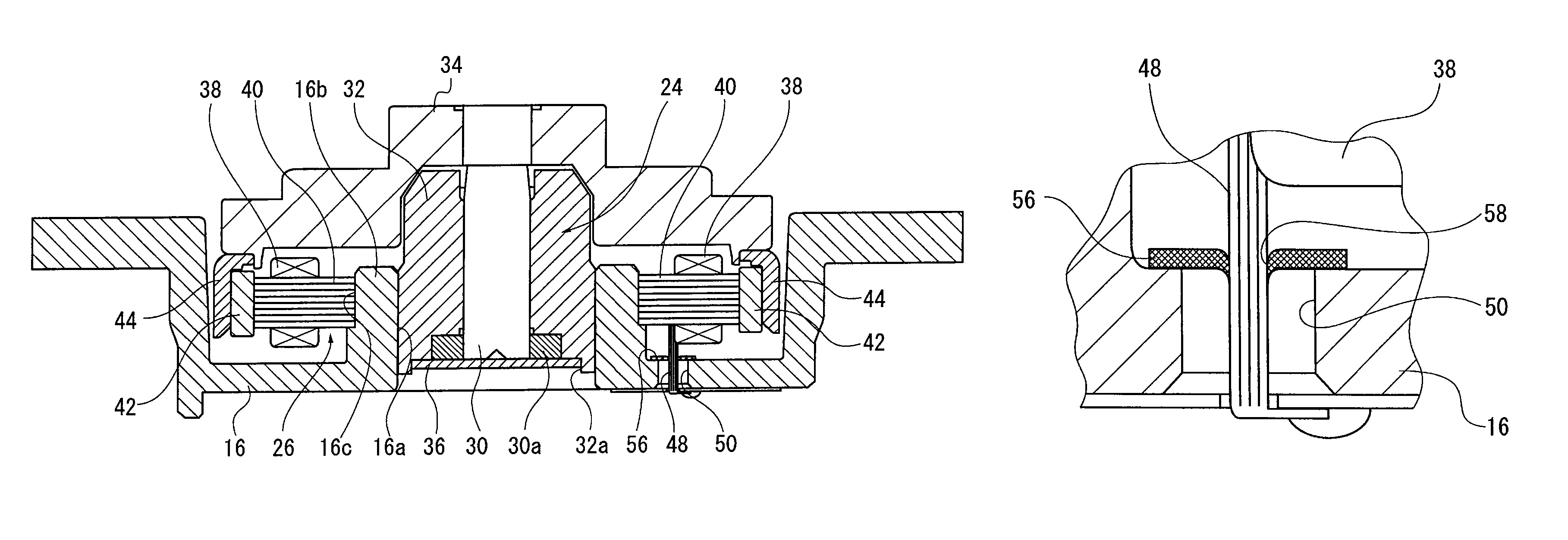
"The present invention provides a disk drive device with a simple structure that achieves stabilization of airtightness of the housing having a through hole. The device includes a housing, a bearing unit, and a drive unit. A sealing sheet is used to seal the through hole and the insertion hole, forming a closed space in the housing. The sealing sheet is made of a fibrous material or resin material and carries a curable resin that is temporarily softened during a curing process and cured afterwards. The curable resin fills the gap between the lead and the insertion hole, ensuring the airtightness of the housing. The size of the insertion hole and the through hole, and the volume of the lead inserted therethrough determine the gap and the volume of curable resin that flows. The condition of sealing by the curable resin does not vary from product to product, stabilizing the airtightness of the disk drive device."

Problems solved by technology

In contrast, the size of dust etc. in the air is far larger so that the dust invading the disk drive device may cause failure of the magnetic head to access the recording disk or cause a physical damage to the recording disk or the magnetic head.
Disadvantageously, this is likely to cause variation in the condition of sealing, causing product to product variation, and resulting in the unstable airtight performance in the through hole portion.
The related-art approach is also disadvantageous in that it requires the addition of a structure for minimizing the flow of whatever is applied or the addition of a step that allows for flowability, resulting in an increase in the manufacturing cost.

Method used


Image

  • Disk drive device having airtight structure with improved airtightness
  • Disk drive device having airtight structure with improved airtightness
  • Disk drive device having airtight structure with improved airtightness

Examples


Embodiment Construction

[0019]The invention will now be described by reference to the preferred embodiments. This does not intend to limit the scope of the present invention, but to exemplify the invention.

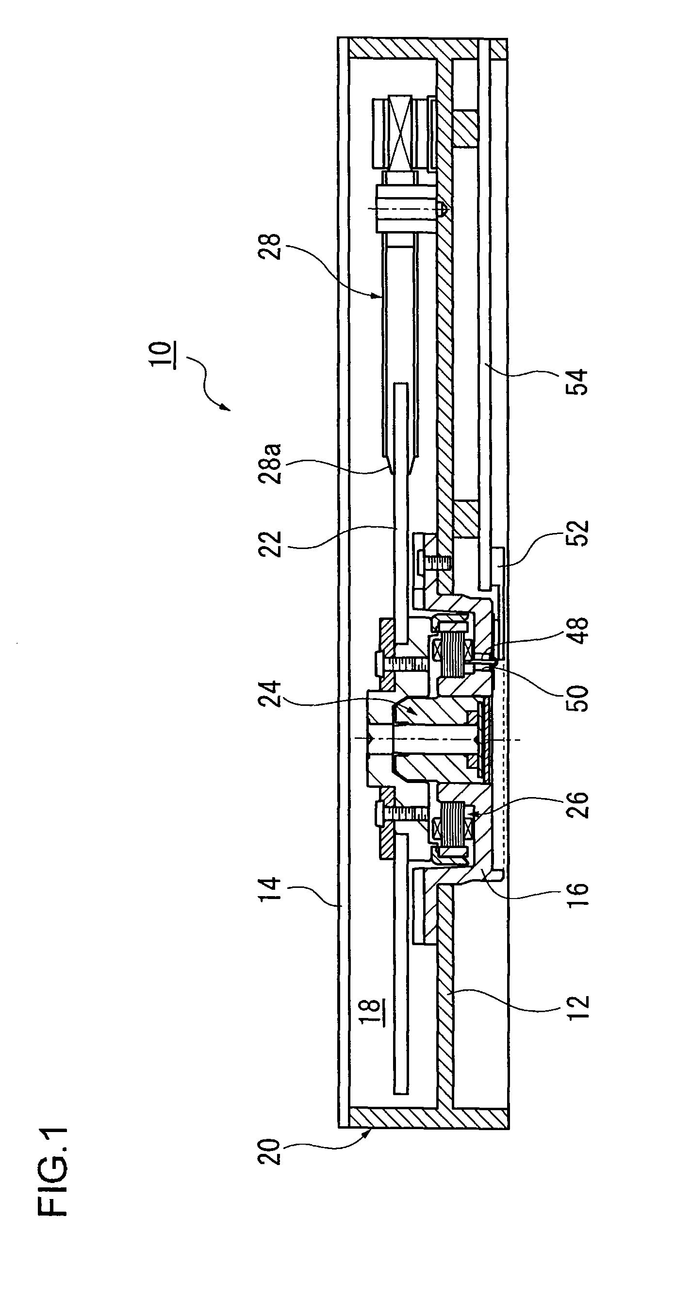
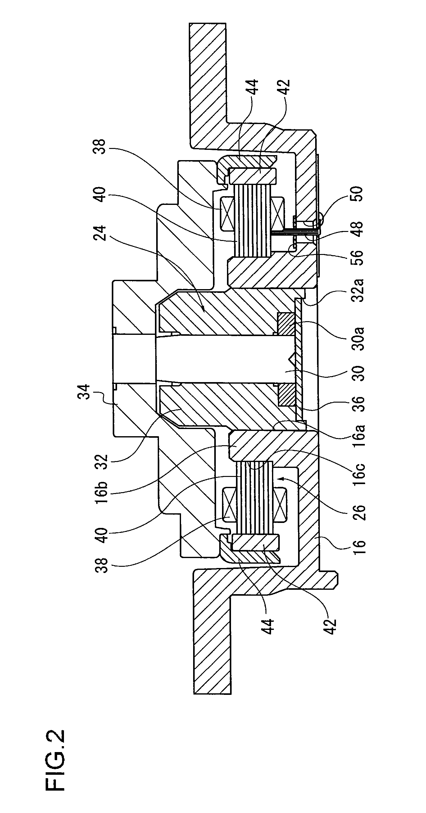
[0020]The disk drive device according to the embodiment is configured such that the housing wall of the device is provided with a first guide. The first guide is a through hole that guides a lead from a driving unit outside. The through hole is covered by a sealing sheet having an insertion hole. The insertion hole is a second guide. The lead is guided from inside the housing via the insertion hole of the sealing sheet. The sealing sheet carries a curable resin. The curable resin, temporarily softened during a curing process, flows into a space between the housing and the through hole and a space between the insertion hole and the lead. The curable resin is cured in this state, ensuring the airtightness of the housing.

[0021]FIG. 1 is a schematic section showing the overall structure of a disk driver devi...


PUM

PropertyMeasurementUnit
diameteraaaaaaaaaa
elasticityaaaaaaaaaa
shapeaaaaaaaaaa

Abstract

A disk drive device is configured such that a wall of a base plate is provided with a through hole that guides a lead from a drive unit outside. The through hole is covered by a sealing sheet having an insertion hole. The lead is guided from inside the housing via the insertion hole of the sealing sheet. The sealing sheet carries a curable resin. The curable resin, temporarily softened during a curing process, flows into a space between the base plate and the through hole and a space between the insertion hole and the lead. The curable resin is cured in this state, ensuring the airtightness of the housing.

Description

CROSS-REFERENCES TO RELATED APPLICATIONS[0001]This application claims priority from Japanese Application No. 2008-164999, filed Jun. 24, 2008 incorporated by reference in its entirety.BACKGROUND[0002]1. Field of the Invention[0003]The present invention relates to disk drive devices and, more particularly, to improvement in the airtight structure of disk drive devices.[0004]2. Description of Related Art[0005]Recently, there has been a rapid development in the technology for improving the recording density of a fixed disk drive device (hereinafter, simply referred to as a disk drive device). In association with this, the recording capacity has been increased dramatically. In association with the improvement in the recording density, measures against the invasion of foreign materials into a disk drive device have become a concern. For example, the distance between the surface of a recording disk accommodated inside a disk drive device and the magnetic head is on the order of several na...

Claims


Application Information

Patent Timeline
Patent Type & Authority Patents(United States)
IPC IPC(8): G11B33/14
CPCG11B33/1466
Inventor TASHIRO, TOMOYUKIFURUI, YOJI
Owner SAMSUNG ELECTRO MECHANICS JAPAN ADVANCED TECHNOLOGY CO LTD
Learn More