Diffuser-nozzle assembly for a turbomachine

a technology of diffuser nozzle and turbomachine, which is applied in the direction of machines/engines, stators, liquid fuel engines, etc., can solve the problems of vibration of the diffuser nozzle, disturbance of the flow of air towards the combustion chamber, etc., and achieve the effect of simple, effective and inexpensiv

Active Publication Date: 2012-03-27
SN DETUDE & DE CONSTR DE MOTEURS DAVIATION S N E C M A
View PDF52 Cites 12 Cited by
  • Summary
  • Abstract
  • Description
  • Claims
  • Application Information

AI Technical Summary

Benefits of technology

[0005]A particular object of the invention is to provide a solution to these problems that is simple, effective, and inexpensive.
[0007]These elastically deformable means enable permanent contact to be guaranteed between the radially outer ends of the vanes and the outer casing, thus making it possible to absorb and damp a fraction of the vibration of the nozzle. These means also guarantee sealing between the radially outer ends of the vanes of the nozzle and the casing during all stages of flight. The flow of air going to the combustion chamber is thus undisturbed by any parasitic flow between the casing and the radially outer ends of the vanes of the nozzle, thereby improving the performance of the turbomachine.
[0015]It may include a sealing coating such as an elastomer, for example, for improving sealing of the contact between the metal sheet and the vanes. It may also include a coating that withstands wear due to the radially outer ends of the vanes rubbing thereagainst.
[0016]The metal sheet may be mounted with resilient prestress when cold between the outer casing and the radially outer ends of the vanes of the nozzle, thus ensuring in operation that the metal sheet is continuously urged elastically against the outer casing and against the radially outer ends of the vanes of the nozzle during all stages of flight.

Problems solved by technology

During other stages of flight, the radially outer ends of the vanes of the nozzle either do not make contact with the casing, thereby allowing air to flow between the tops of the vanes and the casing and thus disturbing the flow of air towards the combustion chamber, or else the tops of the vanes exert excess pressure against the casing.
Furthermore, when the ends of the vanes are not pressed against the casing, the nozzle is subjected to vibration.

Method used


Image

  • Diffuser-nozzle assembly for a turbomachine
  • Diffuser-nozzle assembly for a turbomachine

Examples


Embodiment Construction

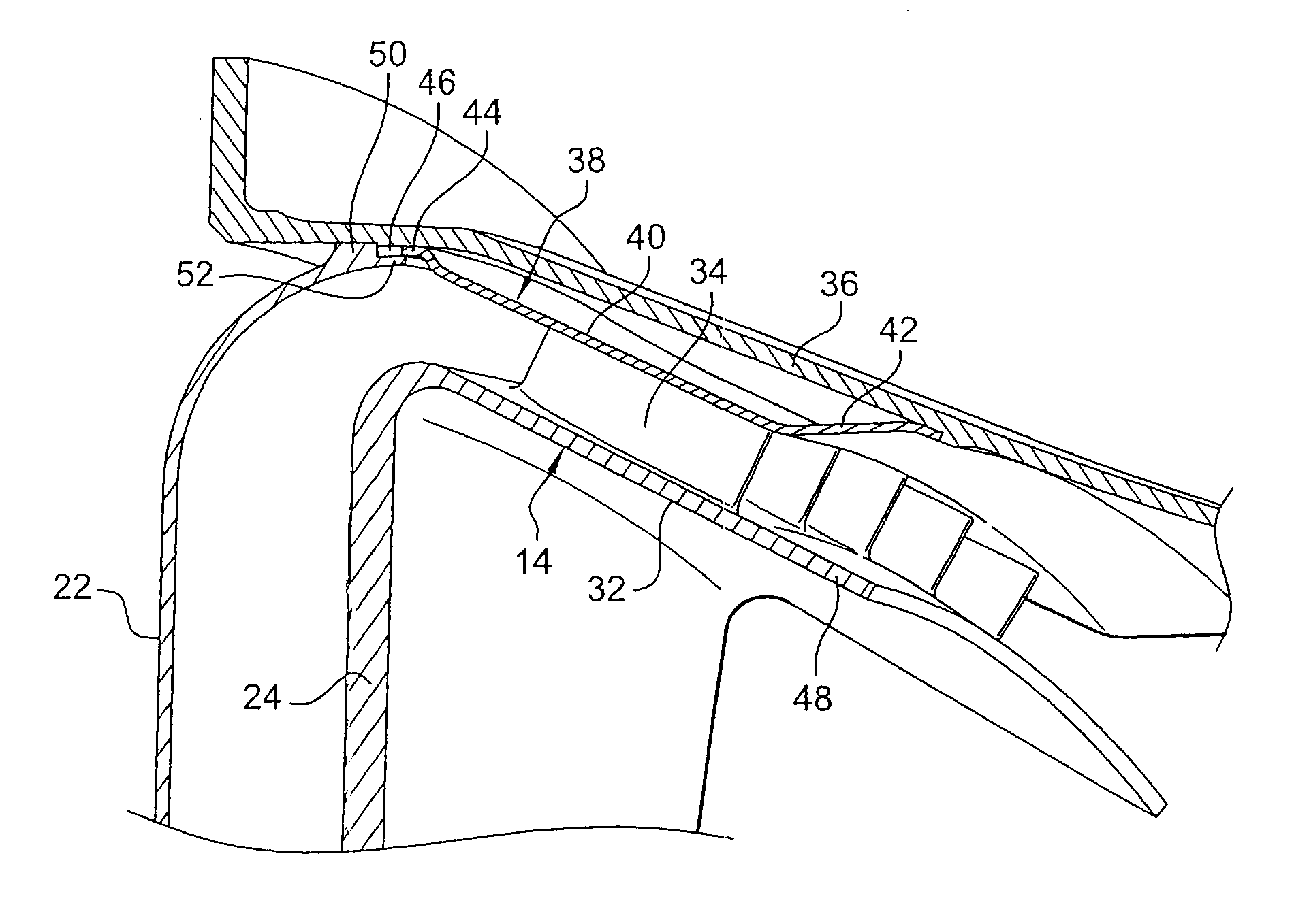
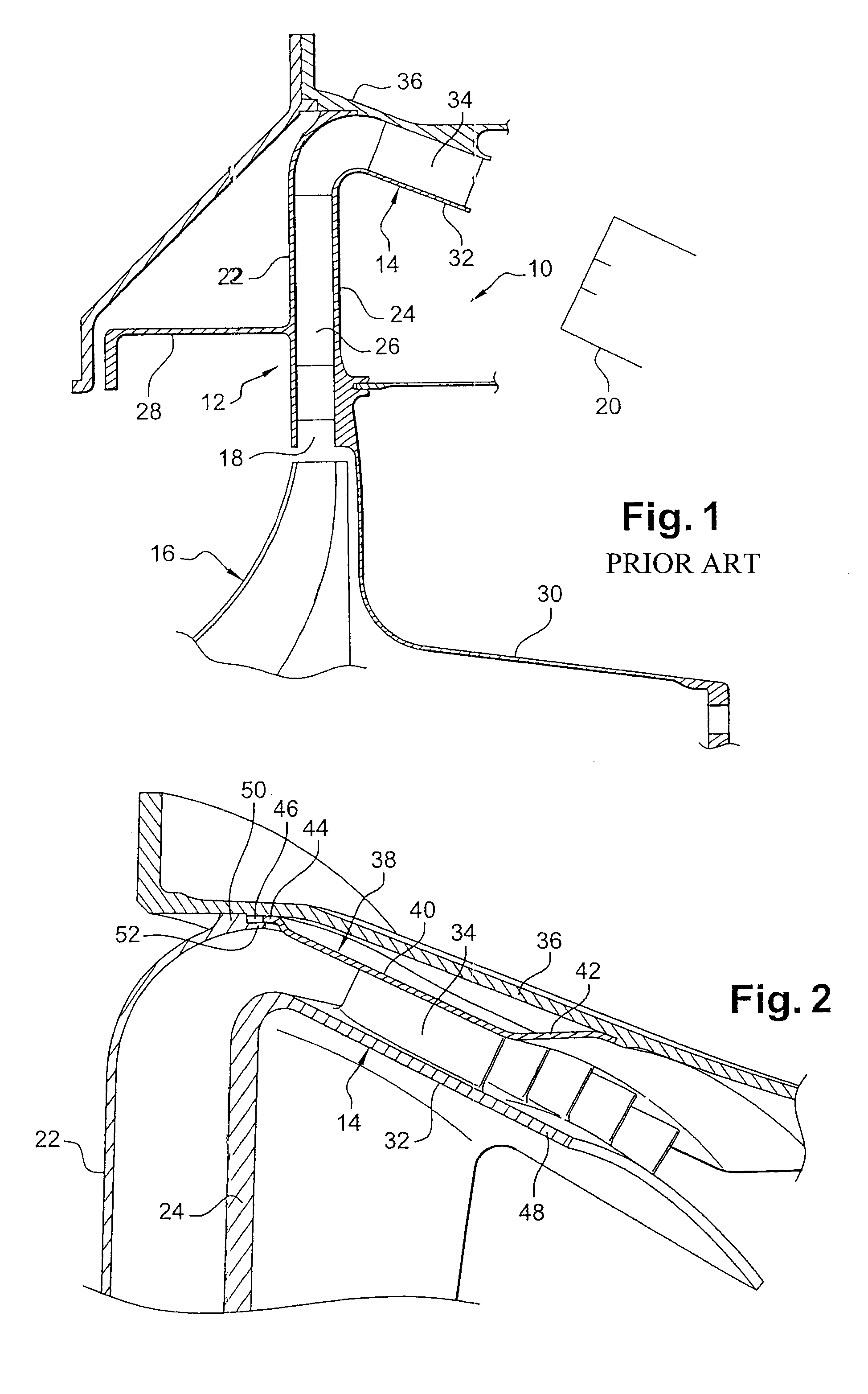
[0023]The diffuser-nozzle assembly 10 shown in FIG. 1 forms part of means for feeding an annular combustion chamber of a turbomachine with air, and it comprises a radial annular diffuser 12 having its outlet connected to an annular nozzle 14, the assembly being for mounting at the outlet from the centrifugal last stage 16 of a compressor of the turbomachine. The inlet 18 of the diffuser 12 is in radial alignment with the outlet from the centrifugal stage 16, and the outlet from the nozzle 14 feeds air to the annular combustion chamber 20, in a manner that is well known to the person skilled in the art.

[0024]The diffuser 12 comprises an upstream annular plate 22 and a downstream annular plate 24, which plates are parallel and extend annularly around the axis of rotation of the compressor, and they are interconnected by vanes 26. The upstream and downstream annular plates 22 and 24 are held in position by respective upstream and downstream annular walls 28 and 30 that are fastened to ...


PUM


Abstract

A diffuser-nozzle assembly mounted at the outlet from a centrifugal compressor is disclosed. The assembly includes a plurality of vanes carried by a radially inner wall forming a surface of revolution and surrounded by an outer casing, elastically deformable devices interposed between the radially outer ends of the vanes of the nozzle and the outer casing. The elastically deformable devices prevent air from passing between the outer casing and the radially outer ends of the vanes.

Description

[0001]The invention relates to a diffuser-nozzle assembly for feeding air to an annular combustion chamber in a turbomachine such as an airplane turbojet or turboprop.TECHNOLOGICAL BACKGROUND OF THE INVENTION[0002]A turbomachine comprises a high pressure compressor having its downstream end opening out to the inlet of a combustion chamber. In certain configurations, where it is desirable to reduce the axial size of the turbomachine, the last compression stage is a centrifugal stage having its outlet surrounded by a radial annular diffuser that is connected to an annular nozzle opening out to the inlet of the combustion chamber. The nozzle comprises a radially inner wall forming a surface of revolution that carries a plurality of vanes surrounded on the outside by a casing that extends downstream around the combustion chamber.[0003]When cold, clearance is provided between the radially outer ends of the vanes of the nozzle and the outer casing. In operation, the nozzle expands radiall...

Claims


Application Information

Patent Timeline
Patent Type & Authority Patents(United States)
IPC IPC(8): F01D1/02
CPCF01D11/005F04D29/083F04D29/441F04D29/444Y02T50/67F05D2240/12F05D2230/642F05D2250/52Y02T50/60
Inventor HERNANDEZ, DIDIER HIPPOLYTELUNEL, ROMAIN NICOLAS
Owner SN DETUDE & DE CONSTR DE MOTEURS DAVIATION S N E C M A
Why Eureka
Try Eureka