Rotational atherectomy device with fluid inflatable support elements and torque transmitting membrane
- Summary
- Abstract
- Description
- Claims
- Application Information
AI Technical Summary
Benefits of technology
Problems solved by technology
Method used
Image
Examples
Embodiment Construction
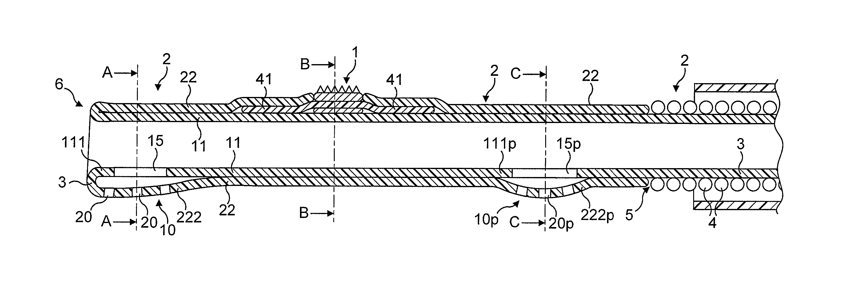
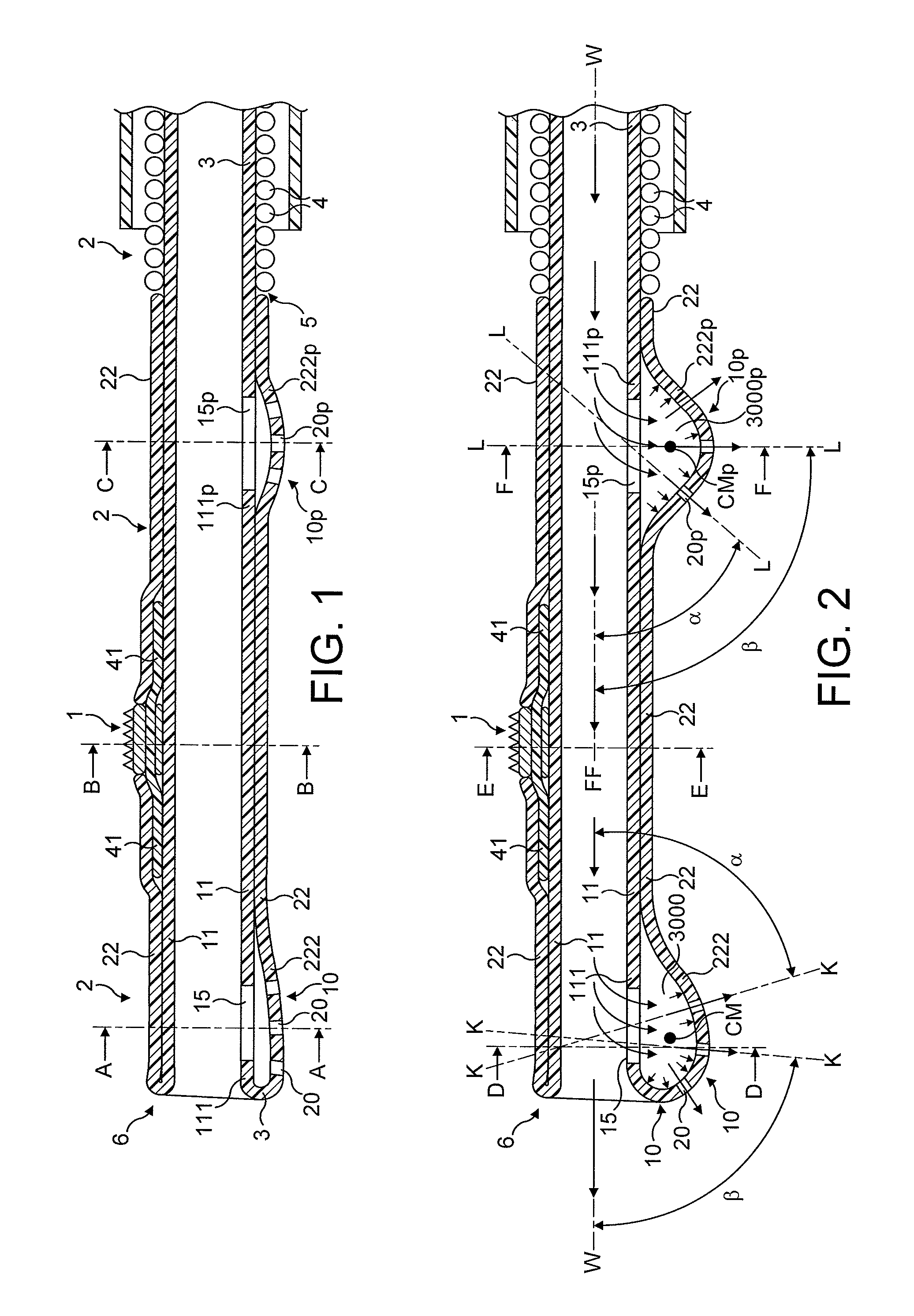
[0087]In FIGS. 1 to 64, the atherectomy device is advanced across the stenotic lesion 330 over the guidewire 250. The direction of movement of the device is indicated by arrow marked “DM”, the antegrade flow of fluid being indicated by arrows “FF” and the flow of fluid in a retrograde direction is indicated by arrows marked “R”. Arrows marked “FP” designate pressure of fluid which distends the support elements. Abraded particles AP abraded from the stenotic lesion 330 are aspirated into a lumen of a drive shaft sheath 260 so that the retrograde flowing fluid and the abraded particles entrained in said fluid can be removed from the treated vessel and out of the patient's body.
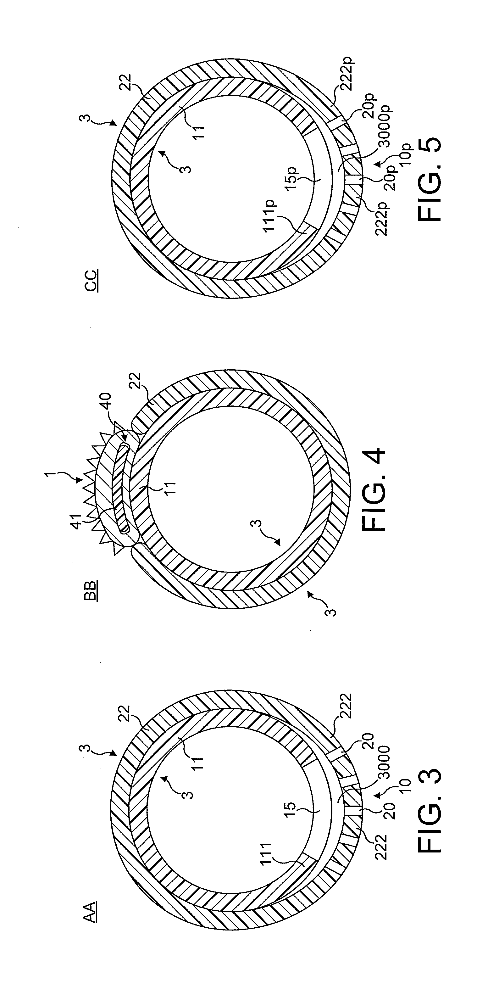
[0088]FIGS. 1 through 8 illustrate in longitudinal and transverse cross-sections a distal portion of the first most preferred embodiment of the rotational atherectomy device of the invention. The rotational atherectomy device is comprised of an abrasive element 1 which is mounted to a rotatable, flexible, hollow...
PUM
 Abstract
Description
Claims
Application Information
 - R&D
- Intellectual Property
- Life Sciences
- Materials
- Tech Scout
- Unparalleled Data Quality
- Higher Quality Content
- 60% Fewer Hallucinations
Browse by: Latest US Patents, China's latest patents, Technical Efficacy Thesaurus, Application Domain, Technology Topic, Popular Technical Reports.
© 2025 PatSnap. All rights reserved.Legal|Privacy policy|Modern Slavery Act Transparency Statement|Sitemap|About US| Contact US: help@patsnap.com


