Endoscope visual imaging and processing apparatus

a visual imaging and processing apparatus technology, applied in the field of endoscope equipment, can solve the problems of loss of smooth and reliable equipment operation, blurred image contour, and difficulty in recognizing images

Inactive Publication Date: 2012-03-27
FUJIFILM CORP
View PDF12 Cites 63 Cited by
  • Summary
  • Abstract
  • Description
  • Claims
  • Application Information

AI Technical Summary

Problems solved by technology

Therefore, the treatment equipment is not appropriately operated, thus, resulting in loss of a smooth and reliable operation of the equipment.
In the above-described invention of JP-A-1-99083, a whole image and enlarged image of the interest area are displayed on the same monitor, which makes narrower the effective area for displaying the respective images, therefore, a problem is brought about that it is difficult of recognize the images.
Therefore, the contour of the image may be blurred to such an extent that an affected part cannot be accurately visualized for the details, depending on an enlargement ratio.

Method used


Image

  • Endoscope visual imaging and processing apparatus
  • Endoscope visual imaging and processing apparatus
  • Endoscope visual imaging and processing apparatus

Examples


embodiment 1

[0014]A. Embodiment 1 of the Present Invention

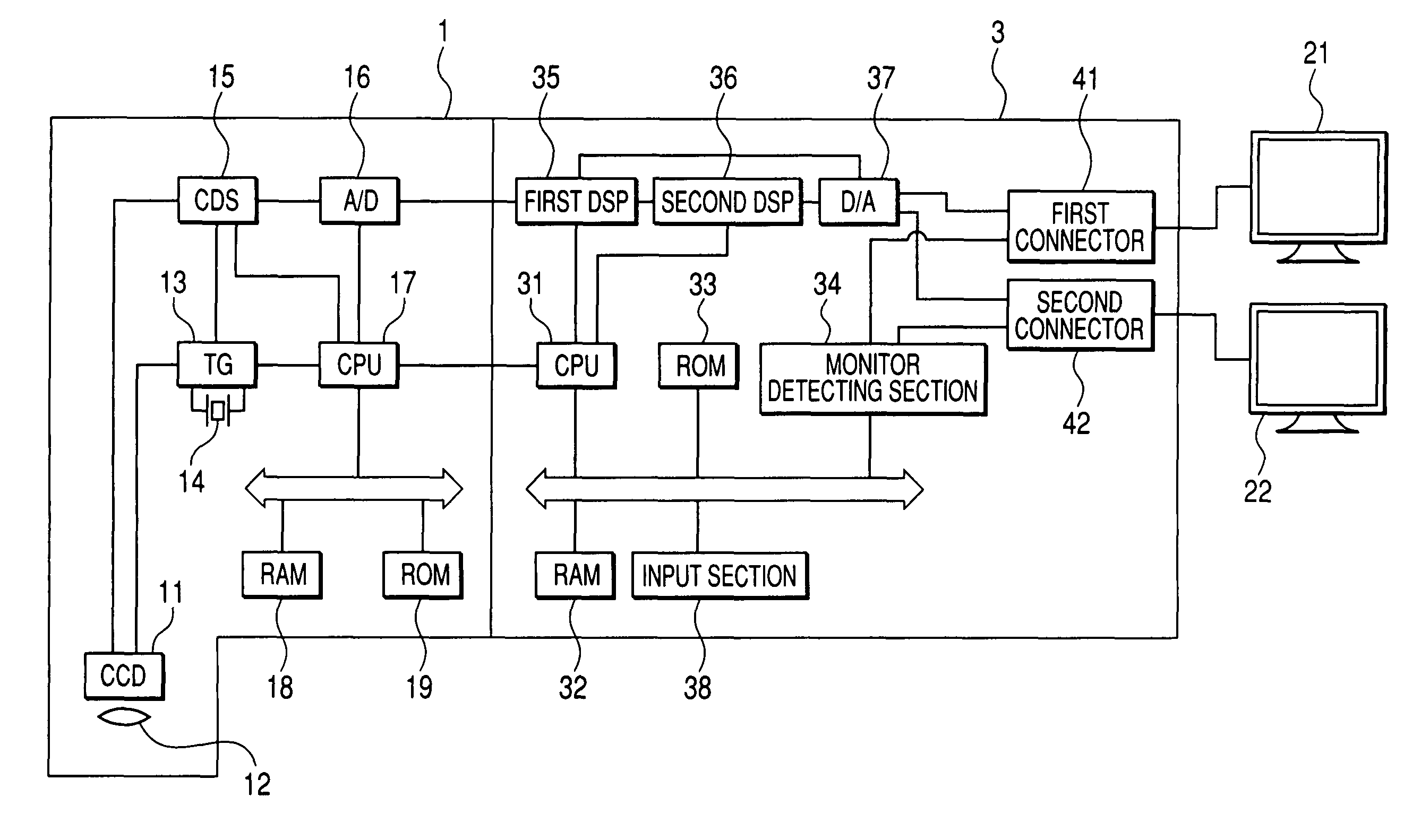
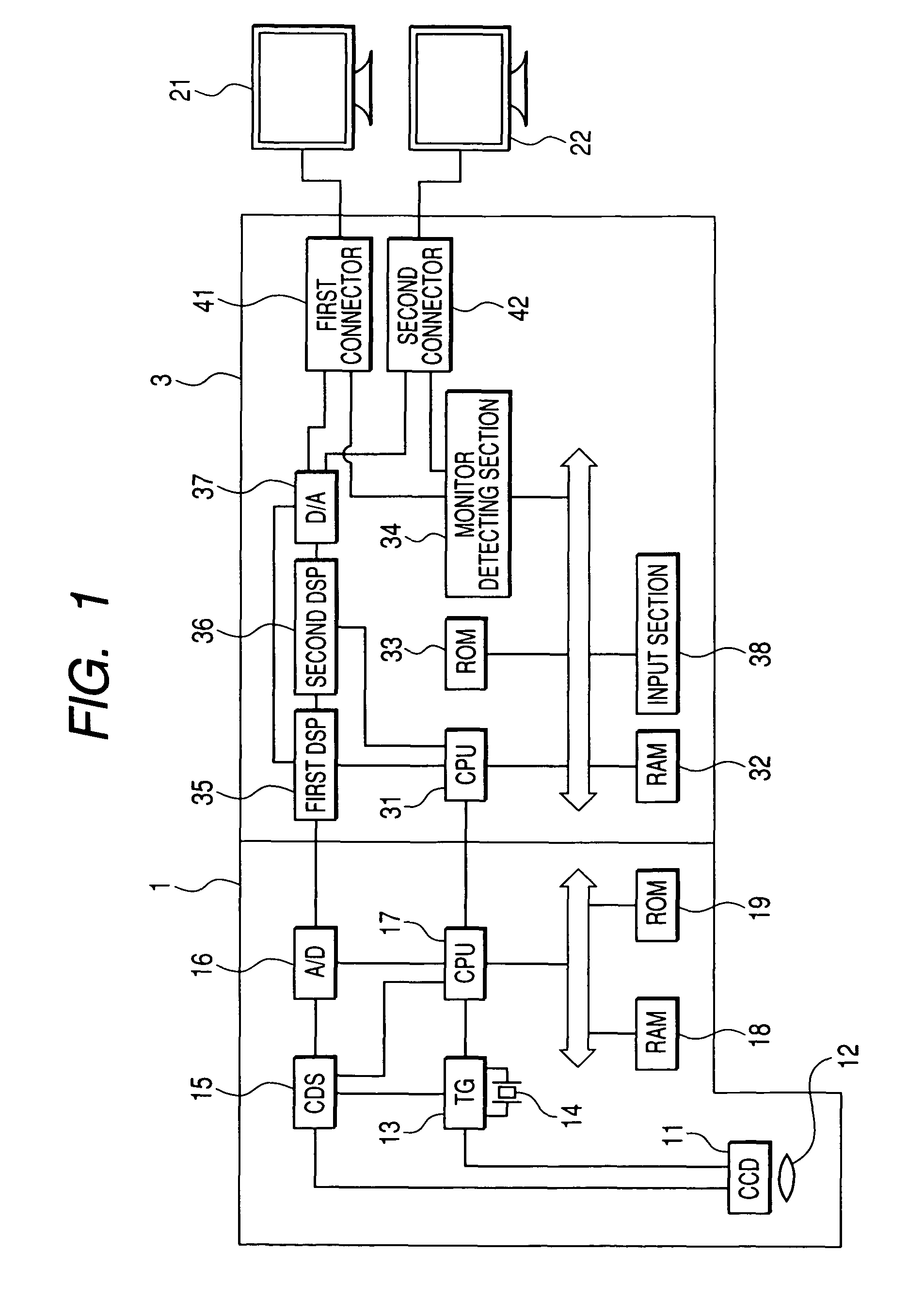
[0015]Hereinafter, a description is given for the embodiment 1 of the present invention. The endoscope apparatus of the present embodiment is constituted by a scope 1 and a processor unit 3, in which the scope 1 is connected to the processor unit 3. Further, a plurality of monitors are connected to the processor unit 3. FIG. 1 shows an example where two monitors are connected thereto.

[0016]The scope 1 is provided with a CCD 11 (solid imaging device), an objective lens 12, a TG (timing generator) 13, a quartz oscillator 14, a CDS (correlated double sampling) 15, an A / D (A / D converter: analog digital converter) 16, a CPU (central processing unit) 17, a RAM (random access memory) 18 and a ROM (read only memory) 19.

[0017]The CCD 11 is an imaging device which radiates to a body to be observed with illumination light supplied from a light source device (not illustrated), subjecting an optical image formed by the objective lens 12 to photoelect...

embodiment 2

[0024]B. Embodiment 2 of the Present Invention

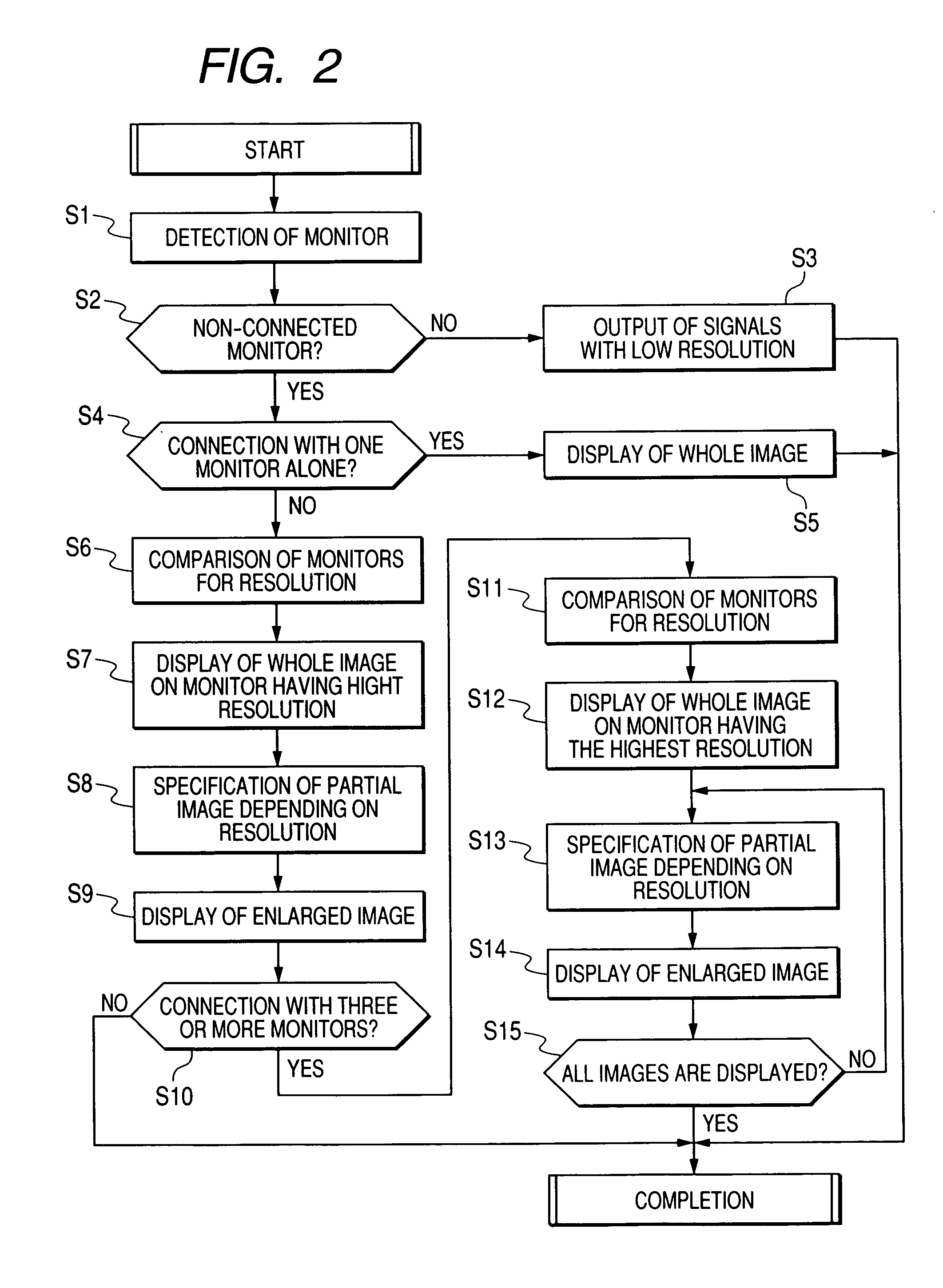
[0025]Next, a description is given for the embodiment 2 of the present invention. As with the embodiment 1, in the embodiment 2, among a plurality of monitors, a whole image is displayed on one monitor and an enlarged partial image is displayed on the rest of monitors. In this instance, it is preferable that the monitor displaying a whole image has a resolution greater than the pixel number of the CCD 11. In order to display an enlarged partial image at a high quality, a plurality of monitors connected to the processor unit 3 have the respective resolutions. The monitor having the highest resolution is used as a monitor for displaying a whole image, whereas the rest of the monitors are used for displaying an enlarged partial image. Hereinafter, the resolution of the monitor for displaying a whole image is equal to or greater than the pixel number of the CCD 11, and the resolution of the monitor(s) for displaying an enlarged partial image...


PUM


Abstract

An endoscope apparatus comprises: a scope comprising a solid imaging device; a processor unit which forms an observation image from signals emitted from the solid imaging device, the processor being connected to the scope; and a plurality of monitors each of which is connected to the processor unit, wherein a whole image of the observation image is displayed on at least one of said plurality of monitors, and a partial image of the observation image is enlarged and displayed on the other one(s) of said plurality of monitors.

Description

BACKGROUND OF THE INVENTION[0001]1. Field of the Invention[0002]The present invention relates to an endoscope apparatus which is inserted into the body of a subject mainly for conducting an endoscopic surgery.[0003]2. Description of the Related Art[0004]An endoscope apparatus such as an electronic endoscope takes an image of a body to be observed which is illuminated by illumination light by using a CCD (charge coupled device), namely, a solid imaging device and gives a predetermined signal processing to the imaged observation image, thereby displaying the image on monitors. An endoscope apparatus is, therefore, provided with a scope loading a CCD and having an insertion portion, a processor unit having a light source for supplying illumination light, which gives a predetermined signal processing to an observation image taken by the CCD, and monitors for displaying the observation image which was subjected to signal processing in the processor unit. This type of endoscope apparatus ...

Claims


Application Information

Patent Timeline
Patent Type & Authority Patents(United States)
IPC IPC(8): G09G5/00G06F3/14A61B1/04A62B1/04H04N5/222
CPCA61B1/00045A61B1/0005A61B1/05H04N7/183
Inventor KAWANISHI, TETSUYAABE, KAZUNORI
Owner FUJIFILM CORP
Why Eureka
Try Eureka