Image sensing apparatus and control method thereof

a technology of image sensing and control method, which is applied in the direction of cameras, television systems, instruments, etc., can solve the problems of shutter blade release, vibration or shock, and the operation characteristic of the shutter device is likely to change, so as to shorten the shooting time per frame and improve the reliability of inadvertent shutter travel

Inactive Publication Date: 2012-04-03
CANON KK
View PDF5 Cites 4 Cited by
  • Summary
  • Abstract
  • Description
  • Claims
  • Application Information

AI Technical Summary

Benefits of technology

[0008]The present invention has been made in consideration of the aforementioned problems, and realizes an image sensing apparatus, which can improve the reliability of inadvertent shutter traveling in a nonuse state and the operation stability of a shutter device after it is left unused for a long term, and can shorten a shooting time per frame.
[0013]According to the present invention, the reliability of inadvertent shutter traveling in a nonuse state and the operation stability of a shutter device after it is left unused for a long term can be improved, and a shooting time per frame can be shortened.

Problems solved by technology

However, in the arrangement which stops the shutter charge mechanism in the travel prepared state in which the charged state is released, the operation characteristic of the shutter device is likely to change, since a vibration or shock acts in a nonuse state of the image sensing apparatus or after an elapse of a long term.
For this reason, an operation after the image sensing apparatus is left in a nonuse state for a long term becomes unstable, or the latched state of the shutter blade may be released and may travel upon acting a vibration or shock.

Method used


Image

  • Image sensing apparatus and control method thereof
  • Image sensing apparatus and control method thereof
  • Image sensing apparatus and control method thereof

Examples


first embodiment

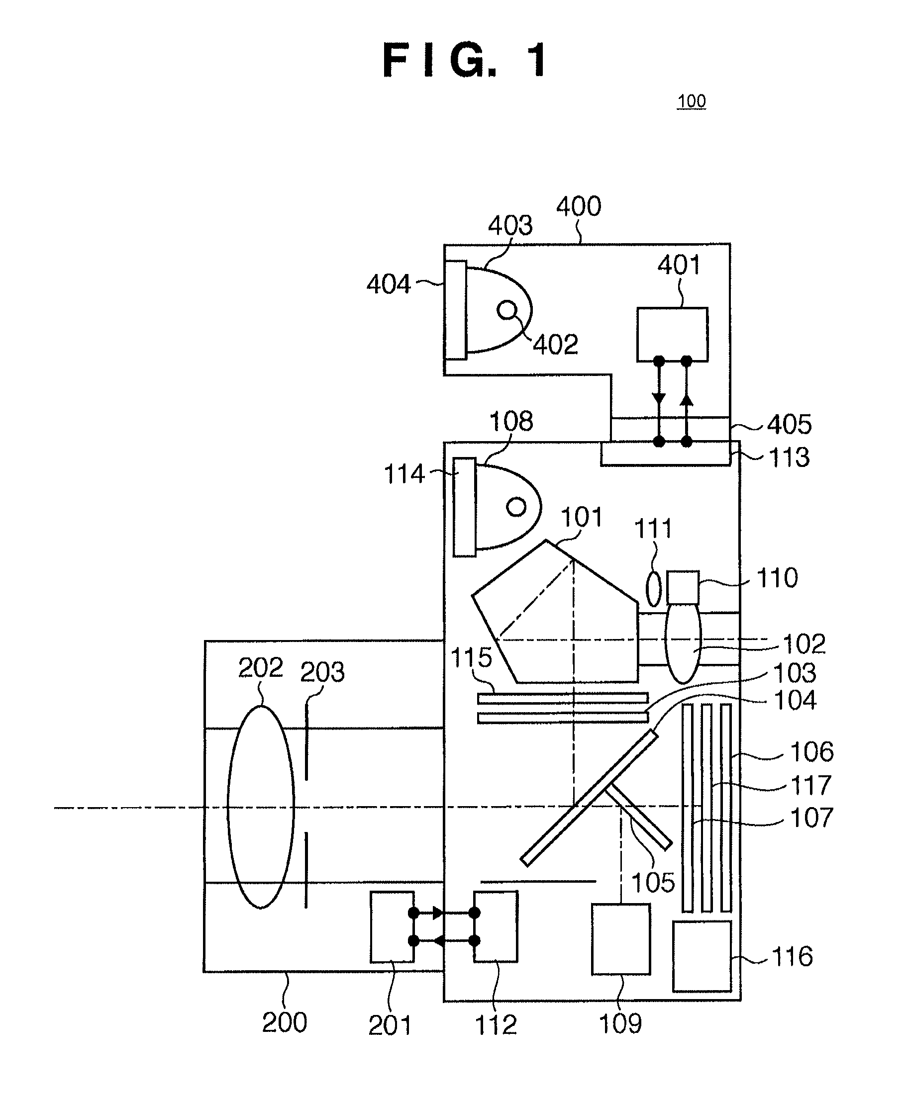
[0032]The mechanical arrangement of an image sensing apparatus according to the first embodiment will be described first with reference to FIG. 1. Referring to FIG. 1, reference numeral 100 denotes an image sensing apparatus such as a digital camera, which can shoot still pictures and movies. Reference numeral 101 denotes an erect orthoscopic optical system which forms a viewfinder optical system; 102, an eyepiece; and 103, a viewfinder screen. Reference numeral 104 denotes a main half mirror (to be referred to as a main mirror hereinafter), which deflects an image sensing light beam to the viewfinder optical system 101; and 105, a sub-mirror which deflects an image sensing light beam to a focus detection unit 109 (to be described later). The main mirror 104 and sub-mirror 105 form an optical path splitting optical system. Reference numeral 106 denotes an image sensing element such as a CCD sensor or CMOS sensor, which photoelectrically converts an image sensing light beam; and 107,...

second embodiment

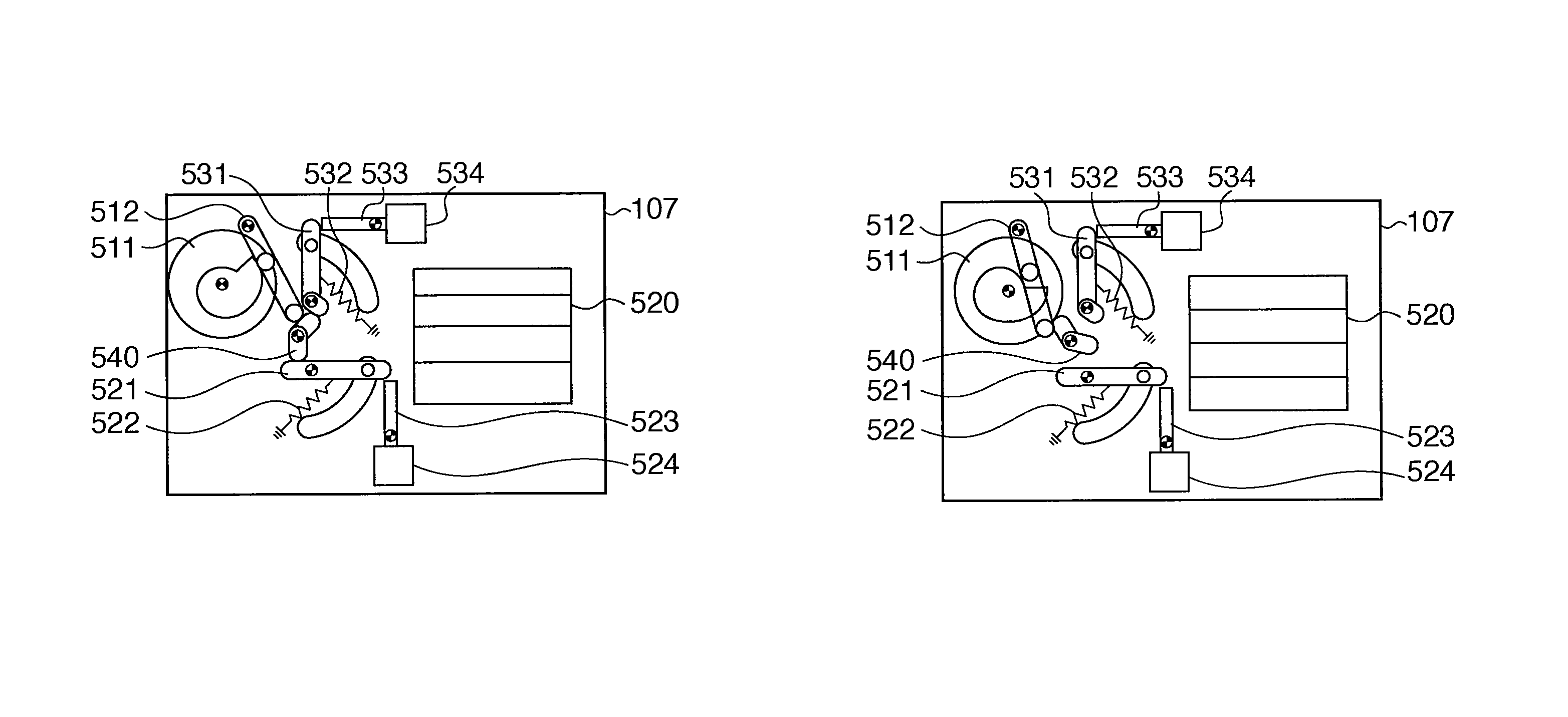
[0104]The second embodiment will be described below. In this embodiment, a description of a part common to the first embodiment will not be repeated. The operation of an electromagnetic shutter device 107 according to the second embodiment will be described below. In this electromagnetic shutter device 107, a latch mechanism that retains a shutter blade is electromagnetically driven to release a latched state. FIG. 11A shows an over-charged state in which a charge operation of the shutter device is complete. FIG. 11B shows a travel prepared state in which the over-charged state of the shutter device is released, and the latch mechanism retains a shutter leading blade group 620 and shutter trailing blade group 630. FIG. 11C shows an exposure state in which the shutter leading blade group 620 traveled, and FIG. 11D shows a travel completed state in which the shutter trailing blade group 630 traveled.

[0105]Referring to FIGS. 11A to 11C, reference numeral 611 denotes a cam gear which is...


PUM


Abstract

An image sensing apparatus comprises a shutter driving member which drives a shutter blade; a shutter spring which urges the shutter driving member; a shutter charge unit which charges the shutter spring, and is switched between an over-charged state and a travel prepared state; a driving unit which drives the shutter charge unit; a retaining unit which, when the shutter charge unit is set in the travel prepared state, retains the shutter driving member in a state in which the shutter spring is charged; a determination unit which determines whether or not the apparatus is executing a continuous shooting operation; and a controller which, when it is determined that the apparatus is executing the continuous shooting operation, controls to drive the shutter charge unit to the travel prepared state without stopping the shutter charge unit in the over-charged state after the charge operation of the shutter spring is complete.

Description

BACKGROUND OF THE INVENTION[0001]1. Field of the Invention[0002]The present invention relates to an image sensing apparatus and control method of the image sensing apparatus, particularly to a shutter control of an image sensing apparatus.[0003]2. Description of the Related Art[0004]Conventionally, an arrangement, which retains a shutter blade by a shutter latch mechanism after a charge operation of a shutter device is completed by a shutter charge mechanism, and stops the shutter charge mechanism in a travel prepared state in which the charged state by the shutter charge mechanism is released, is known. As another arrangement, after the charge operation by the shutter charge mechanism is completed, the shutter charge mechanism is stopped in the charged state to retain the shutter blade. Then, the shutter charge mechanism is shifted from the charged state to the travel prepared state interlockingly with a shutter release operation, thus attaining a shooting operation.[0005]Japanese ...

Claims


Application Information

Patent Timeline
Patent Type & Authority Patents(United States)
IPC IPC(8): G03B17/38G03B9/40H04N5/238G03B9/36G03B17/00G03B19/12H04N5/225
CPCG03B17/38
Inventor NAKAGAWA, KAZUYUKI
Owner CANON KK
Why Eureka
Try Eureka