Electrical cable provided with external marking and method of crimping the barrel of a contact onto an electrical cable provided with external marking

a technology of electrical cables and barrels, which is applied in the direction of cables, insulated conductors, conductors, etc., can solve the problems of increased risk of defective crimping joints, increased risk of producing intermittent defective contacts, and inability to verify the position of cables in the barrel of contacts

Active Publication Date: 2012-04-03
AIRBUS OPERATIONS (SAS)
View PDF9 Cites 15 Cited by
  • Summary
  • Abstract
  • Description
  • Claims
  • Application Information

AI Technical Summary

Benefits of technology

[0009]Another aspect of the disclosed embodiments is to provide a means of verifying the position of the cable in the barrel of a contact before crimping so as to guarantee that the cable is properly positioned in the barrel and that there is correct electrical continuity along the cable and the contact. Another aspect of the disclosed embodiments is to provide a method for reliable electrical crimping of a barrel onto a cable, irrespective of the nature of the conducting core of the cable.

Problems solved by technology

However, it is sometimes necessary to use a contact in which the barrel does not have a peephole or in which the peephole is obstructed.
However, it is then no longer possible to verify the position of the cable in the barrel of the contact before crimping, since the barrel has no peephole or the peephole is obstructed.
As a result, there is a greater risk of defective crimped joints.
Poor crimping of the barrel onto the cable may in particular incur the risk of producing an intermittently defective contact, or the risk of heating the cable, or the risk of the connection between the cable and the contact undergoing accelerated aging, or the risk of a loss of function of the electronic system provided with this defective connection.

Method used


Image

  • Electrical cable provided with external marking and method of crimping the barrel of a contact onto an electrical cable provided with external marking
  • Electrical cable provided with external marking and method of crimping the barrel of a contact onto an electrical cable provided with external marking
  • Electrical cable provided with external marking and method of crimping the barrel of a contact onto an electrical cable provided with external marking

Examples


Embodiment Construction

)

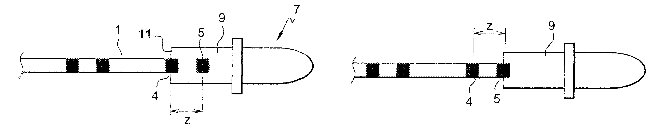
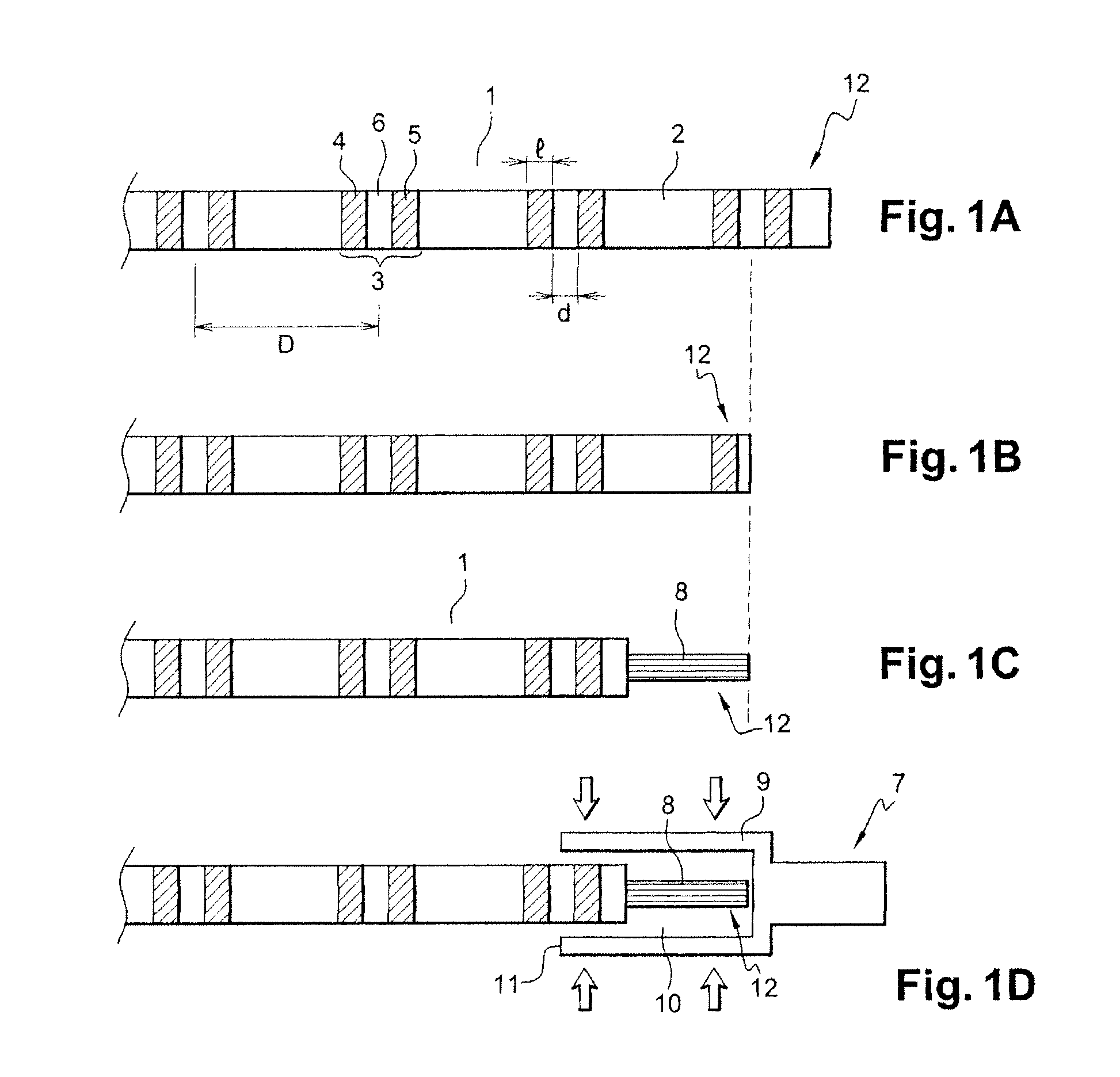
[0036]FIG. 1A shows an example of a cable provided with external marking according to the disclosed embodiments.

[0037]The cable 1 has an insulating external sheath 2. The marking consists of a block 3 of two consecutive patterns 4, 5 separated from each other by an unmarked region 6. The two consecutive patterns 4, 5 of the block 3 of patterns are consecutive along the length of the cable 1. The term “length of the cable 1” is understood to mean the longest dimension of the cable 1, parallel to the longitudinal axis of said cable 1. The block 3 of patterns is repeated several times along the cable 1.

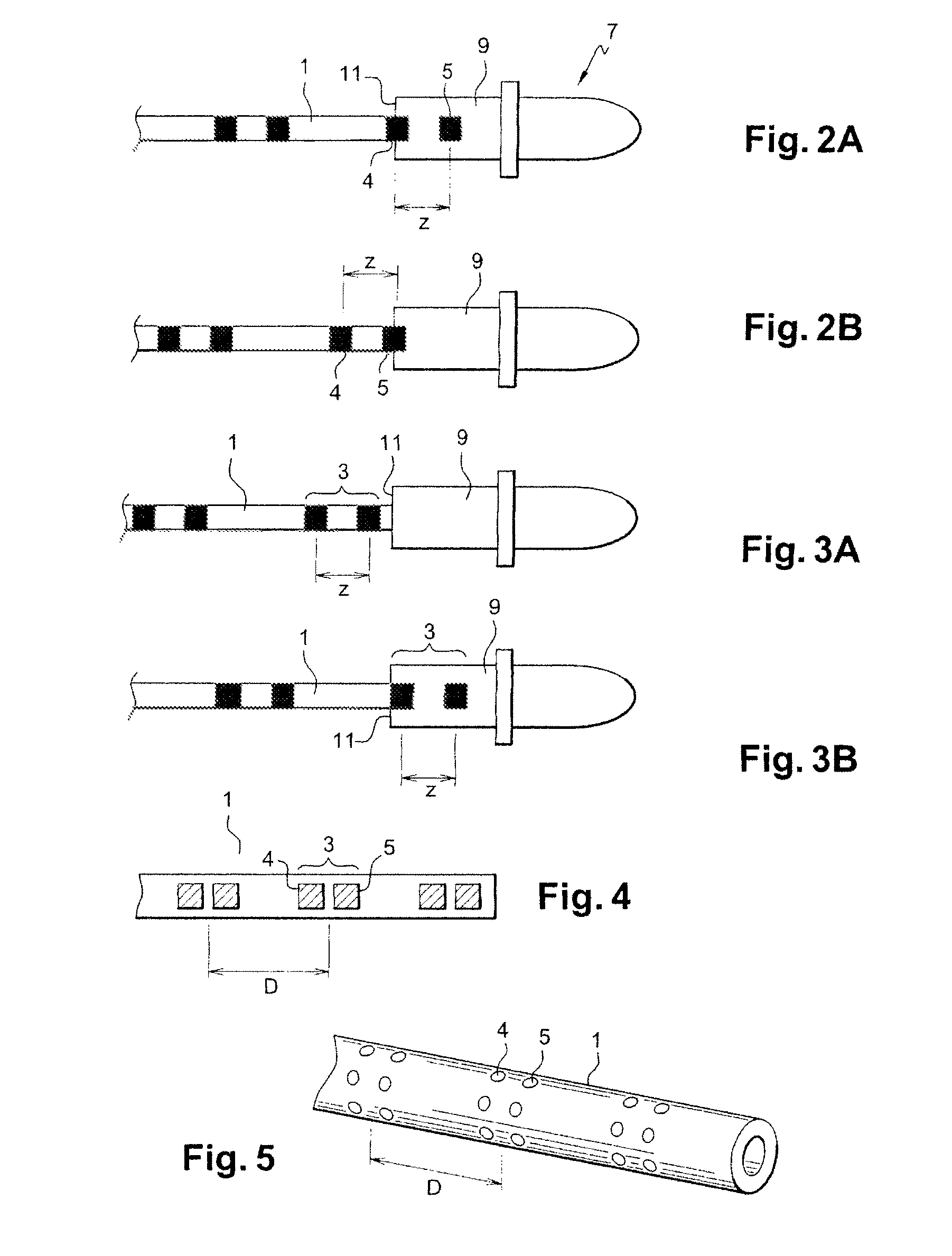
[0038]In the example shown in FIG. 1A, the patterns 4, 5 are rings surrounding the cable 1 in its diameter. The patterns 4, 5 are therefore continuous over the entire cross section of the cable 1. In other exemplary embodiments, it is possible to produce external marking with different patterns.

[0039]In FIG. 4, the patterns 4, 5 of the blocks 3 of patterns are squares. It is possible to...


PUM

PropertyMeasurementUnit
widthaaaaaaaaaa
widthaaaaaaaaaa
widthaaaaaaaaaa

Abstract

An electrical cable (1) provided with a sheath (2) having external marking. The marking is formed from a block (3) of two patterns (4, 5), the two patterns being consecutive along a length of the cable, said block being repeated at least twice along the length of the cable starting from the free end (12) of the cable. The disclosed embodiments also relates to a method of crimping a contact (7) onto such a cable, the external marking of the cable making it possible to know the position of the cable in the barrel and thus guarantee that the crimping that takes place will be of good quality.

Description

CROSS-REFERENCE TO RELATED APPLICATIONS[0001]This application is the National Stage of International Application No. PCT / FR2006 / 001293, filed on Jun. 1, 2006, which designated the United States of America, and which international application was published under PCT Article 21(2) as WO Publication No. WO 2006 / 134251 A1 and which claims priority from French Application No. 0551593, filed Jun. 14, 2005.BACKGROUND[0002]1. Field[0003]The disclosed embodiments relate to an electrical cable provided with external marking that allows the position of the cable in a barrel that has to be crimped onto said cable to be checked. The disclosed embodiments also relate to a method of crimping a barrel onto such a cable. More precisely, the disclosed embodiments relate to marking visible to the naked eye, provided on the sheath of the cable, said marking being repeated so as to make it possible, by a simple visual check, to ensure that the cable is correctly positioned in the barrel before the barre...

Claims


Application Information

Patent Timeline
Patent Type & Authority Patents(United States)
IPC IPC(8): H01B7/00
CPCH01B7/36H01R43/048Y10T29/49181
Inventor AUPHAND, JEROMERUFFEL, REGIS
Owner AIRBUS OPERATIONS (SAS)
Why Eureka
Try Eureka