Device for estimating information on target object

a technology for estimating information and target objects, applied in measurement devices, using reradiation, instruments, etc., can solve the problems of reducing the detection distance of the apparatus, difficult for the radar apparatus to distinguish an unnecessary reflection object, and the height of the object cannot be detected by the radar apparatus, etc., to achieve the effect of low computing load

Active Publication Date: 2012-04-03
DENSO CORP
View PDF11 Cites 18 Cited by
  • Summary
  • Abstract
  • Description
  • Claims
  • Application Information

AI Technical Summary

Benefits of technology

[0016]A subordinate object of the present invention is to provide a device which is mounted in a vehicle and estimates, at a low computing load, information on a target object indicating that the target object has no possibility of collision with the vehicle or has a probability of collision with the vehicle.
[0020]Accordingly, because the height of the target object is estimated from the collation of the actual null point pattern with the modeled null point patterns, the computing load required for this estimation can be reduced, and the height of the target object can be estimated as information on the target object at a low computing load.
[0024]Accordingly, the device can distinguish the target object having a probability of collision with the vehicle from the target object having no possibility of collision with the vehicle, and information indicating a probability of collision with the vehicle or no possibility of collision with the vehicle can be obtained as information on the target object, at a low computing load.

Problems solved by technology

This radar apparatus cannot detect the height of the object (i.e., information on the object in the height direction).
Therefore, it is difficult for the radar apparatus to distinguish an unnecessary reflecting object having no possibility of collision with the controlled vehicle from an obstacle (e.g., an object dropped on the road or a forward vehicle running in front of the controlled vehicle) having a probability of collision with the controlled vehicle.
However, when the vehicle is placed at a point at which the road gradient (i.e., inclination of the road in the vertical direction) is changed, the detecting distance of the apparatus is reduced, and the apparatus cannot detect the obstacle which is away from the vehicle by a distance longer than the reduced detecting distance.
Therefore, it is improper to excessively narrow the beam width in the vertical direction.
The radar wave reflected from a target object returns to the radar apparatus through a plurality of transmission paths, and the reflected waves transmitted through the respective paths interfere with each other in the radar apparatus.
However, the computing load required to detect heights of many target objects becomes large.
Therefore, a processor having a high throughput is inevitably required.
However, it is impossible to distinguish an obstacle, which is placed on the road and has a probability of collision with the vehicle, from an unnecessary reflecting object (e.g., a signboard or a traffic signal located over the road at a high position) under which the vehicle can pass.

Method used


Image

  • Device for estimating information on target object
  • Device for estimating information on target object
  • Device for estimating information on target object

Examples


embodiment

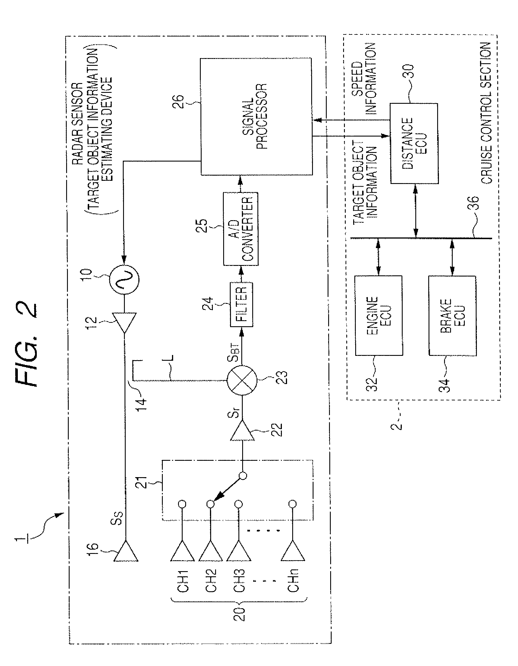
[0036]FIG. 2 is a block diagram of a vehicle control system with a radar sensor acting as a target object information estimating device according to this embodiment. As shown in FIG. 2, a vehicle control system mounted in a controlled vehicle has a radar sensor 1 for radiating radar waves and receiving radar waves reflected from target objects to produce information about the target objects from the radiated and received waves, and a cruise control section 2 for performing cruise control for the controlled vehicle according to the information.

[0037]The radar sensor 1 is formed of a frequency modulated continuous wave (FM CW) type electronically agile radar. This sensor 1 radiates a beam of frequency-modulated radar waves, set in the millimeter wave band, in the running direction of the vehicle and receives waves reflected from each of objects. The sensor 1 acts as a target object information estimating device which detects the objects from the radiated and received radar waves, reco...


PUM


Abstract

A target object information estimating device embodied by an electronically agile radar sensor is mounted in a moving vehicle. The device has a unit outputting a radar wave every measuring period, receiving radar waves reflected from a target object through different transmission paths and calculating a distance to the object in each measuring period to detect the object, a unit tracking the object in a tracking term of measuring periods, a unit setting the distance changed with time as a null distance each time electric power of the received waves is reduced to a minimal value, and a unit producing an actual pattern of null points corresponding to the null distances, collating the actual pattern with modeled patterns corresponding to various heights and estimates the height of the object from the collation result as information about the object.

Description

CROSS-REFERENCE TO RELATED APPLICATION[0001]This application is based upon and claims the benefit of priority of the prior Japanese Patent Application 2009-162773 filed on Jul. 9, 2009, so that the contents of which are incorporated herein by reference.BACKGROUND OF THE INVENTION[0002]1. Field of the Invention[0003]The present invention relates to a device for estimating information on a target object existing around a vehicle by radiating a radar wave and receiving the wave reflected from the object.[0004]2. Description of Related Art[0005]A millimeter wave radar apparatus located in a controlled vehicle has been used to detect information on a target object existing around the vehicle. This radar apparatus radiates a beam of radar wave set in the millimeter wave band as a high-frequency signal while mechanically or electrically scanning the wave in the horizontal direction (i.e., a width direction of the vehicle) and detects, from the wave reflected from the object, a distance fro...

Claims


Application Information

Patent Timeline
Patent Type & Authority Patents(United States)
IPC IPC(8): G01S13/00G01S13/931
CPCG01S13/345G01S13/931G01S2013/462G01S2013/9353G01S2013/9325G01S2013/9346G01S2013/935G01S2013/9321G01S2013/9319G01S2013/93185G01S2013/932
Inventor SAMUKAWA, YOSHIEMATSUOKA, KEIJISHIMIZU, KOUJI
Owner DENSO CORP
Why Eureka
Try Eureka