Liquid crystal display device, polarizing plate and backlight source
a technology of liquid crystal display device and polarizing plate, which is applied in the direction of instruments, non-linear optics, optics, etc., can solve the problem of remarkable color change, and achieve the effect of effectively controlling hue chang
- Summary
- Abstract
- Description
- Claims
- Application Information
AI Technical Summary
Benefits of technology
Problems solved by technology
Method used
Image

Examples
first embodiment
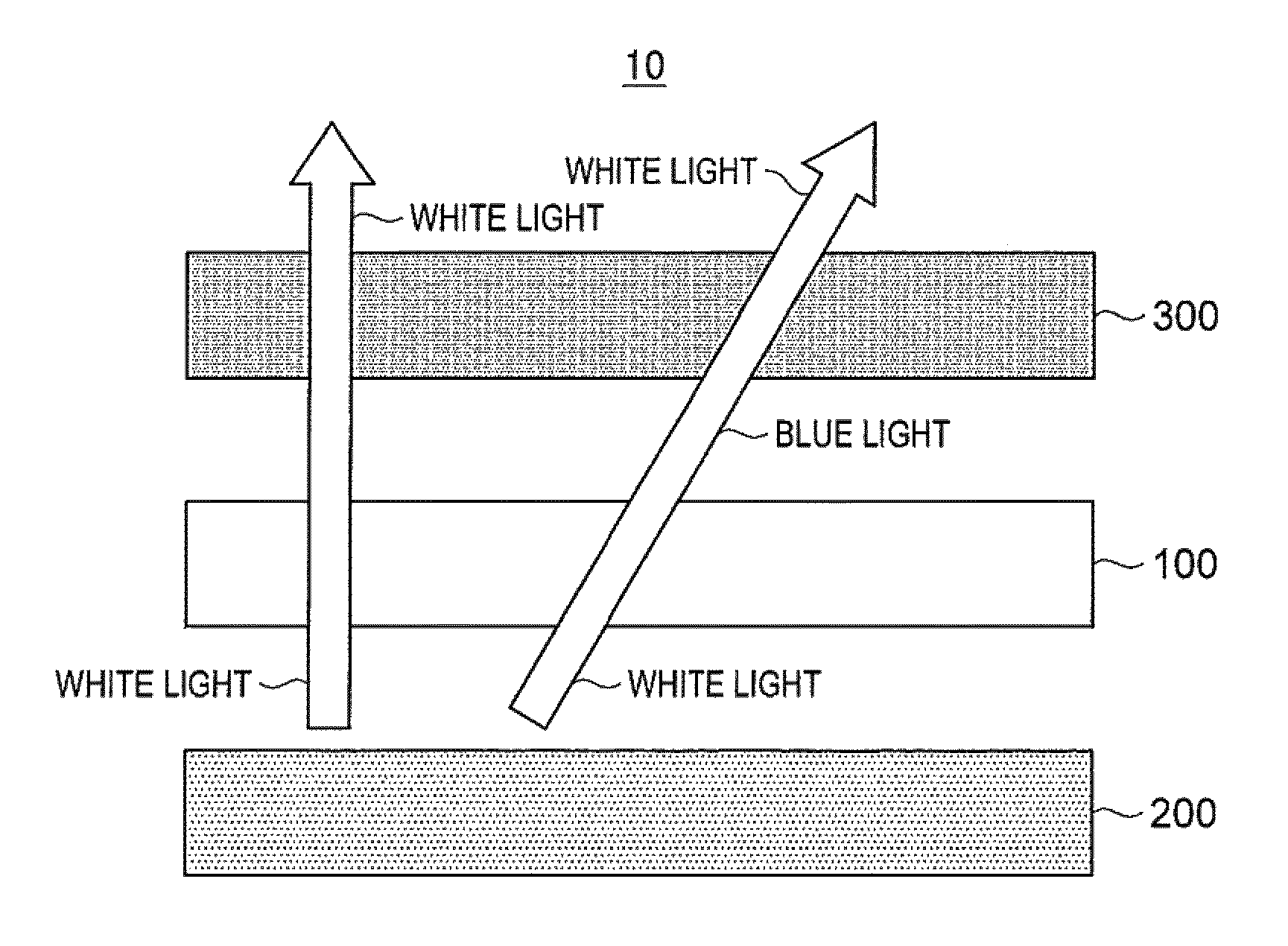
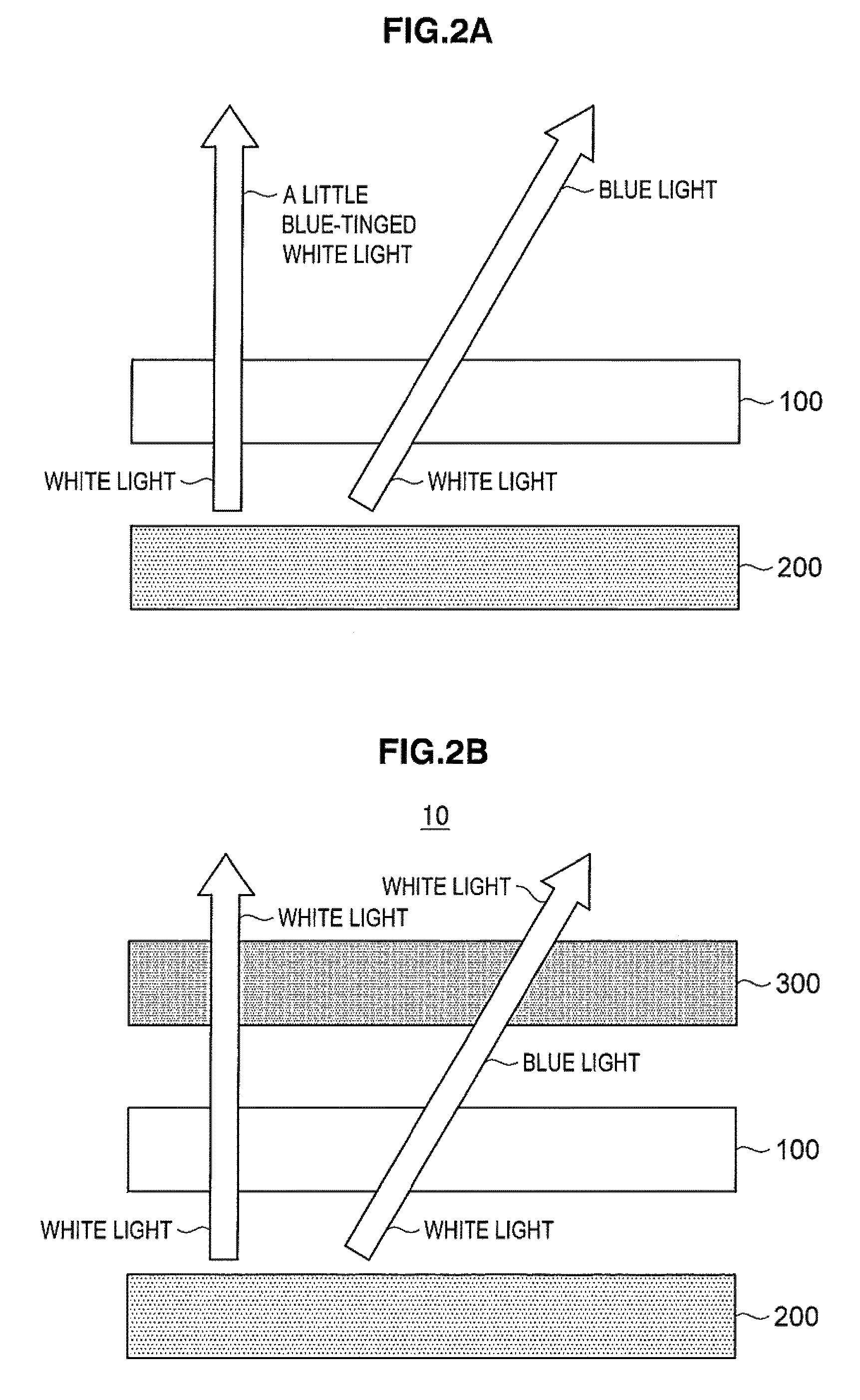
[0040]With reference to FIGS. 2A and 2B, an outline of a liquid crystal display device according to a first embodiment of the invention will be described in detail. FIGS. 2A and 2B are view for explaining the outline of the liquid crystal display device having an absorbing layer according to the embodiment.
[0041]As shown in FIG. 2A, an absorbing layer 100 according to the embodiment absorbs a predetermined wavelength band from the white light illuminated from a backlight source 200. As mentioned above with reference to FIG. 6, a hue change occurs in the white light passing through the liquid crystal panel in the oblique direction from the normal of the liquid crystal panel. The absorbing layer 100 according to the embodiment is formed to absorb the wavelength band corresponding to the color change into which the white light is changed after passing through the liquid crystal panel obliquely. When the white light passes through the liquid crystal panel obliquely as shown in FIG. 6, t...
example 1
[0085]At first, the liquid crystal display device 10 including the absorbing layer 100 described below, the backlight source 200, and the liquid crystal panel 300 is manufactured.
[Backlight Source 200]
[0086]A cold-cathode tube of three wavelength types is used as the backlight source 200.
[Polarizing Plate 301]
[0087]A neutral gray for TV is used as the polarizing plate 301. The single transmittance of the polarizing plate 301 is 40 to 42% and the polarization degree is 99.9% or more.
[Liquid Crystal Cell 351]
[0088]The nematic liquid crystal with the wavelength dispersion of the refractive index R(450 nm) / R(590 nm)=1.08 is used as the liquid crystal layer 355, and the thickness of the liquid crystal layer 355 is adjusted so that the product d·Δn of the double refractive index Δn of the liquid crystal and the thickness d of the liquid crystal layer is 0.28 to 0.35 μm.
[Absorbing Layer 100]
[0089]The optical sheet including the pigment for absorbing the same color light as the color (yello...
example 2
[0093]A liquid crystal display device having the adhesive layer 311 also working as the absorbing layer is manufactured by adding the pigment while adjusting the pigment density to the adhesive layer 311 of the polarizing plate 301 arranged at the side of the backlight source 200, instead of having the absorbing layer with the dyed polymer film. The same backlight source 200 and the same liquid crystal cell 351 as those in the Example 1 are used. A change of the color coordinates in the liquid crystal display device is measured in the same way as in the Example 1.
PUM
| Property | Measurement | Unit |
|---|---|---|
| absorption wavelength | aaaaa | aaaaa |
| transmittance | aaaaa | aaaaa |
| wavelength | aaaaa | aaaaa |
Abstract
Description
Claims
Application Information
 - R&D
- Intellectual Property
- Life Sciences
- Materials
- Tech Scout
- Unparalleled Data Quality
- Higher Quality Content
- 60% Fewer Hallucinations
Browse by: Latest US Patents, China's latest patents, Technical Efficacy Thesaurus, Application Domain, Technology Topic, Popular Technical Reports.
© 2025 PatSnap. All rights reserved.Legal|Privacy policy|Modern Slavery Act Transparency Statement|Sitemap|About US| Contact US: help@patsnap.com