
Optical film, production method of optical film, optically-compensatory film, polarizing plate and liquid crystal display device

a technology of optical film and polarizing plate, which is applied in the direction of polarizing elements, manufacturing tools, instruments, etc., can solve the problems of so-called color shift phenomenon, black display when obliquely observed is colored in blue or red, and cannot be overcome. , to achieve the effect of reducing distan

Inactive Publication Date: 2013-01-08
FUJIFILM CORP
View PDF4 Cites 0 Cited by
  • Summary
  • Abstract
  • Description
  • Claims
  • Application Information

AI Technical Summary

Benefits of technology

The present invention relates to an optical film that can reduce the tint change of a liquid crystal display at different viewing angles. The optical film needs to meet certain formulae and requirements to achieve this. The technical effect of this invention is to provide an improved viewing experience for liquid crystal displays by reducing the tint change at various angles.

Problems solved by technology

However, in these methods, only the light leakage for a certain wavelength region (for example, green light near 550 nm) is reduced, and light leakage for other wavelength regions (for example, blue light near 450 nm or red light near 650 nm) is not taken into consideration.
Therefore, the problem of so-called color shift which is a phenomenon that black display when obliquely observed is colored in blue or red cannot be overcome.

Method used


Image

  • Optical film, production method of optical film, optically-compensatory film, polarizing plate and liquid crystal display device
  • Optical film, production method of optical film, optically-compensatory film, polarizing plate and liquid crystal display device
  • Optical film, production method of optical film, optically-compensatory film, polarizing plate and liquid crystal display device

Examples


example 1-1

Production of Cellulose Acylate Solution CA-1

[0614]Cellulose Acylate Solution CA-1 is prepared by charging the following composition into a mixing tank and stirring it to dissolve respective components. Here, Ac indicates an acetyl group.

[0615]

(Composition of Cellulose Acylate Solution CA-1)Cellulose acetate having Ac substitution100.0parts by massdegree of 2.81TPP (triphenyl phosphate)7.8parts by massBDP (biphenyl diphenyl phosphate)3.9parts by massMethylene chloride (first solvent)402.0parts by massMethanol (second solvent)60.0parts by mass

(Preparation of Matting Agent Solution MT-1)

[0616]20 Parts by mass of silica particle having an average particle diameter of 16 nm (AEROSIL R972, produced by Nihon Aerosil Co., Ltd.) and 80 parts by mass of methanol are thoroughly mixed with stirring for 30 minutes to prepare a silica particle liquid dispersion. This liquid dispersion is charged into a disperser together with the composition shown below and further stirred for 30 minutes or more...

example 1-2

Production of Optical Film 112

[0623]Cellulose Acylate Film 101 obtained above is fed to the same stretching apparatus as used in Example 1-1. The film temperature is set at 190° C. and after 30 seconds, the film is passed through a heating zone. Thereafter, stretching is started. The film is shrunk to 0.85 times in the longitudinal direction and stretched to 1.25 times in the width direction by using the tenter clips, whereby Optical Film 112 having a thickness of 135 μm after stretching is obtained.

example 1-3

Production of Optical Film 113

[0624]Cellulose Acylate Film 101 obtained above is fed to the same stretching apparatus as used in Example 1-1. The film temperature is set at 175° C. and after 30 seconds, the film is passed through a heating zone. Thereafter, stretching is started. The film is relaxed and 0.85 times in the longitudinal direction and stretched to 1.25 times in the width direction by using the tenter clips, whereby Optical Film 113 having a thickness of 115 μm after stretching is obtained.


PUM

PropertyMeasurementUnit
aspect ratioaaaaaaaaaa
wavelength regionsaaaaaaaaaa

Abstract

A production method of an optical film, including: a stretching step of stretching a film, wherein the film has a longitudinal direction, a width direction and a thickness direction, wherein the stretching is in either of the longitudinal direction or the width direction of the film; and a shrinking step of shrinking the film in either of the longitudinal direction or the width direction of the film, that is not the direction in which the film is stretched, wherein the film thickness in the thickness direction is increased as compared with the film thickness before at least one of the stretching step and the shrinking step.

Description

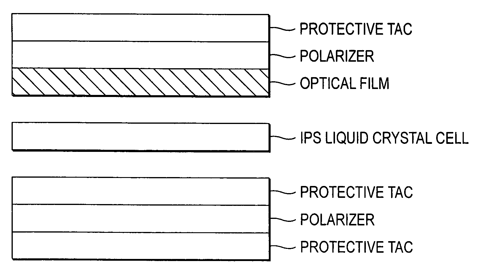
BACKGROUND OF THE INVENTION[0001]1. Field of the Invention[0002]The present invention relates to an optical film having a high contrast ratio over a wide range and capable of suppressing the color shift, a production method of the optical film, and an optically-compensatory film, a polarizing plate and a liquid crystal display device each using the optical film.[0003]2. Description of the Related Art[0004]A liquid crystal display device is widely used for a monitor of personal computers or potable devices or for a television because of its various advantages such as low voltage / low power consumption and capability of size and thickness reduction. For such a liquid crystal display device, various modes are proposed according to the aligned state of liquid crystal molecules in the liquid crystal cell. Conventionally, a TN mode having such an aligned state as that liquid crystal molecules are twisted at about 90° toward the upper substrate from the lower substrate of the liquid crystal...

Claims


Application Information

Patent Timeline
Patent Type & Authority Patents(United States)
IPC IPC(8): G02F1/1335G02B6/10C03B37/022
CPCB29C55/08B29D11/0073C08L1/10C08L1/12G02F1/133634G02F1/134363B29K2001/00B29K2001/12B29K2995/0034G02B5/30G02F2001/133637G02F1/133637
Inventor NAKAYAMA, HAJIMEITO, YOJI
Owner FUJIFILM CORP
Learn More