Wave guide that attenuates evanescent light of higher order TM mode

a waveguide and evanescent light technology, applied in the field of waveguides and thermally assisted magnetic recording elements, can solve the problems of reducing the energy ratio of the fundamental mode, reducing the magnetic stability of the magnetic micro particle, and reducing the coercive force of the magnetic recording medium, etc., to achieve the effect of improving the energy ratio with respect to the fundamental mod

Active Publication Date: 2012-04-03
TDK CORPARATION
View PDF16 Cites 21 Cited by
  • Summary
  • Abstract
  • Description
  • Claims
  • Application Information

AI Technical Summary

Benefits of technology

[0015]The penetration length of evanescent light is determined in each mode, and it is known that the length is short in the fundamental mode, and is long in the higher order mode. The light absorbing element is placed at an offset distance which is shorter than the penetration length of evanescent light in the higher order mode but is longer than that in the fundamental mode. Consequently, light in the fundamental mode passes through the core substantially as is, and light in the higher order mode is absorbed by the light absorbing element and passes through the core after transition to a lower energy. As described above, the light absorbing element, which is a characteristic part of the present invention, functions as a type of filter in the higher order mode, and enables the energy ratio with respect to the fundamental mode to be improved. Furthermore, as described above, the waveguide in this specification is used as a term indicating the structure including the core and the clad surrounding the core.

Problems solved by technology

However, if the magnetic micro particles are decreased in size, thermal stability of magnetization of the magnetic micro particles is reduced.
However, if the anisotropic energy of the magnetic micro particles is increased, coercive force of the magnetic recording medium becomes great and it becomes difficult to record information in the existing magnetic head.
Such a trilemma exists in conventional magnetic recording, which is a great obstacle to increasing the recording density.
Normal light cannot be tapered (narrowed) to a region that is smaller than the wavelength of the light due to a diffraction limitation.
In the plasmon antenna, the near field light is generated by directly irradiating light, but in this technique, a conversion efficiency of the irradiated light to the near field light is low.
The end part positioned on the ABS of the MR element is away from the magnetic recording medium, and as a result, there is the problem that a servo signal recorded in the magnetic recording medium cannot be read at the time of recording movement.

Method used


Image

  • Wave guide that attenuates evanescent light of higher order TM mode
  • Wave guide that attenuates evanescent light of higher order TM mode
  • Wave guide that attenuates evanescent light of higher order TM mode

Examples


Embodiment Construction

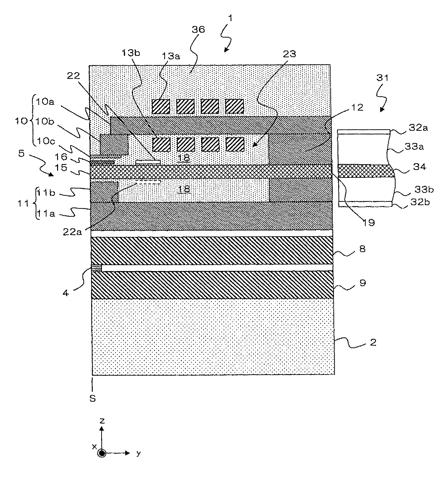
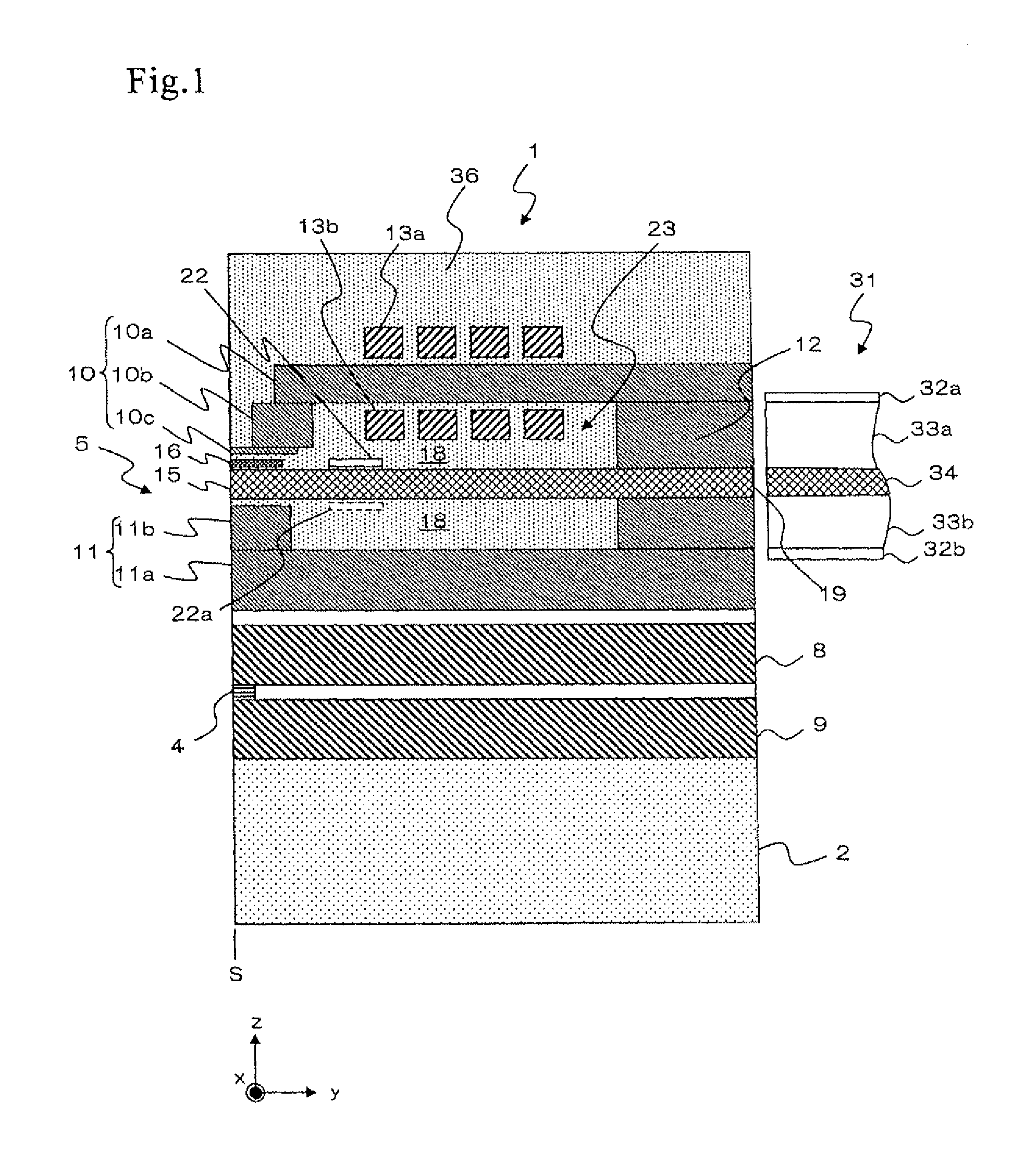
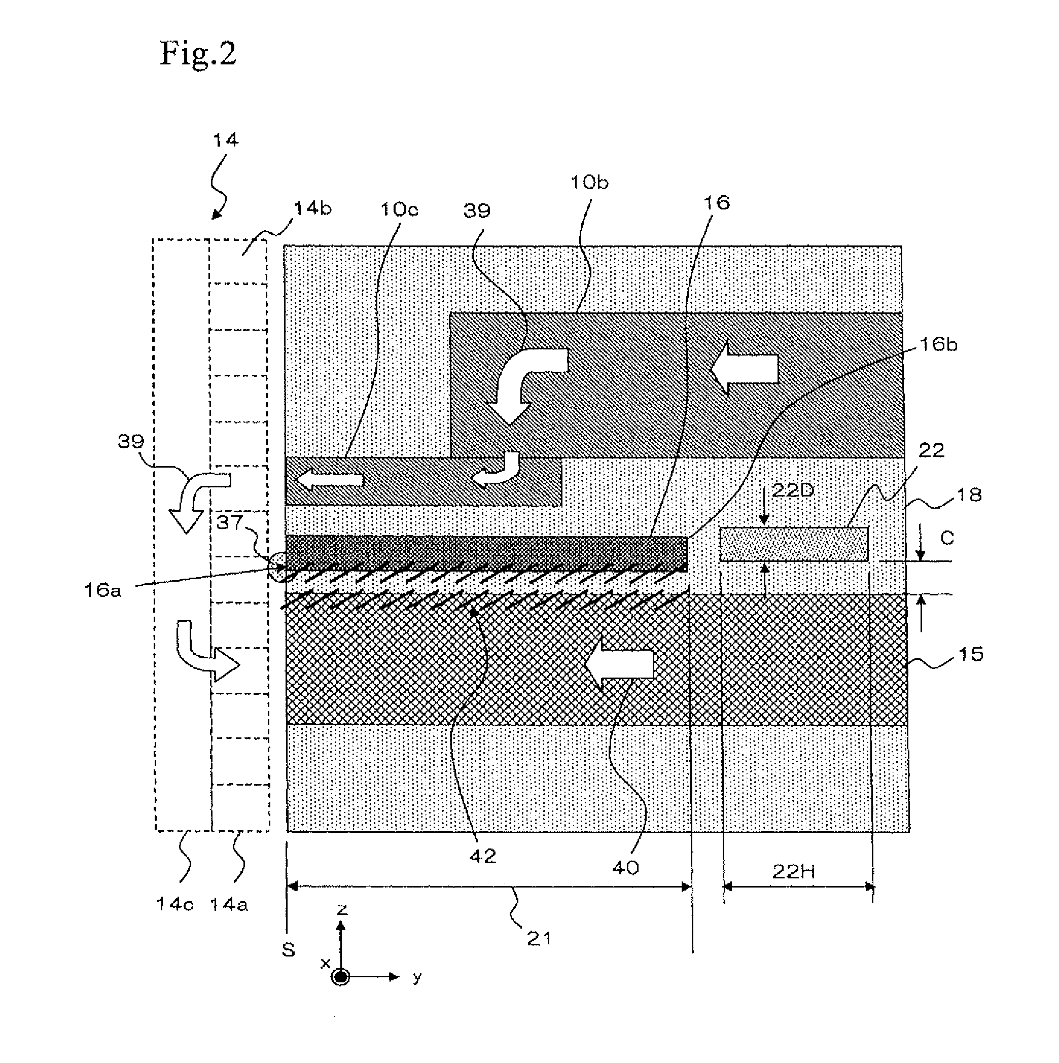
[0037]The magnetic recording element of the present invention is described with reference to the drawings. FIG. 1 a cross sectional view of main parts of the slider including the magnetic recording element of the present invention. A slider 1 is configured by laminating an MR element 4 forming a reproductive head part and a magnetic recording element 5 forming a recording head part on a substrate 2 made from ALTIC (Al2O3—TiC). Furthermore, in the explanation hereafter, “lamination direction” means a film formation direction in a wafer process, and it is matched with the direction z in various diagrams. “Upper side of the lamination direction” means a direction orientating toward an overcoat layer 36 from the substrate 2, and “lower side of the lamination direction” means a direction orientating toward the substrate 2 from the overcoat layer 36.

[0038]The slider 1 has the reproductive head part equipped with the MR element 4 positioned by exposing its tip portion to an air bearing sur...


PUM

PropertyMeasurementUnit
distanceaaaaaaaaaa
distanceaaaaaaaaaa
thicknessaaaaaaaaaa

Abstract

A waveguide has a core through which laser light can propagate in a TM mode, that has a rectangular cross section perpendicular to a propagative direction of the laser light, and through which the laser light can propagate in a fundamental mode in which only one portion exists on the cross section of the core where a light intensity of the laser light becomes maximal, and a higher order mode in which two or more portions exist where the light intensity becomes maximal, a clad surrounding the core, and a light absorbing element in the clad, and wherein a distance between the light absorbing element and the core is shorter than a penetration length of evanescent light in the higher order mode, but is longer than a penetration length of evanescent light in the fundamental mode.

Description

BACKGROUND OF THE INVENTION[0001]1. Field of the Invention[0002]The present invention relates to a wave guide (or waveguide) and a thermally-assisted magnetic recording element using this waveguide.[0003]2. Description of the Related Art[0004]Recently, in a magnetic recording device, such as a hard disk device, performance improvement of a thin film magnetic head and a magnetic recording medium is in demand in association with high recording density. As the thin film magnetic head, a combination type thin film magnetic head is widely used, where a reproducing head having a magneto resistive effect element (hereafter, also referred to as magneto resistive (MR) element) for reading, and a recording head having an inducible electromagnetic conversion element (magnetic recording element) for writing are laminated onto a substrate. In a hard disk device, the thin film magnetic head is placed in a slider that flies slightly above the surface of the magnetic recording medium.[0005]A magnet...

Claims


Application Information

Patent Timeline
Patent Type & Authority Patents(United States)
IPC IPC(8): G11B11/00
CPCG11B5/3116G11B5/314G11B5/6088G11B2005/0021
Inventor KOMURA, EIJIHARA, SHINJITAKAYAMA, SEIICHISHIMAZAWA, KOJI
Owner TDK CORPARATION
Why Eureka
Try Eureka