
Amount-of-compressed data control method and image data compressing apparatus

a data control and data amount technology, applied in the field of amount of compressed data control and image data compression apparatus, can solve the problems of preventing stable image quality, reducing the accuracy of image quality, and difficulty in estimating recording time and/or transmission time, so as to reduce the variation of scale factor

Inactive Publication Date: 2012-04-03
SONY CORP
View PDF11 Cites 0 Cited by
  • Summary
  • Abstract
  • Description
  • Claims
  • Application Information

AI Technical Summary

Benefits of technology

This approach stabilizes image quality by minimizing data variations, allowing accurate estimation of recording or transmission time, and ensuring the compressed data fits within planned storage or transmission bands, thereby enhancing data management efficiency.

Problems solved by technology

By the way, the amount-of-data control method has a problem in recording compressed data to a recording medium or transmitting compressed data through a communication path that the compressed data to be recorded does not fit into a predetermined storage area or may not be transmitted in a predetermined transmission band if the amount of data based on the estimated scale factor has a plus error in a case where the amount of data is larger or smaller than planned.
Conversely, it is difficult to estimate the recording time and / or transmission time if the error is minus and large though no problems may occur regarding the recording area and / or transmission band.
Further increases of the error in amount of data may occur since it is difficult for a compressor having a characteristic not expressible by a single relational expression to estimate an optimum scale factor though the processing above uses a single relational expression to estimate a scale factor.
As a result, the amount of data varies, which prevents stable image quality.

Method used


Image

  • Amount-of-compressed data control method and image data compressing apparatus
  • Amount-of-compressed data control method and image data compressing apparatus
  • Amount-of-compressed data control method and image data compressing apparatus

Examples


Embodiment Construction

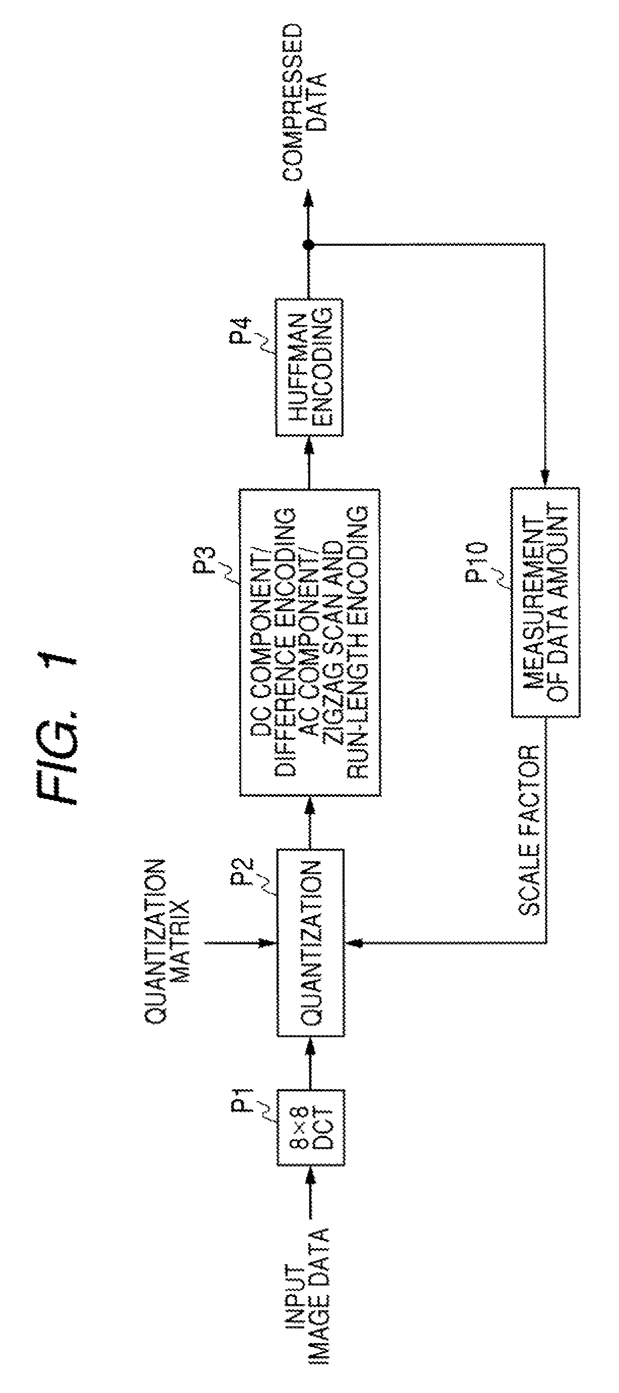
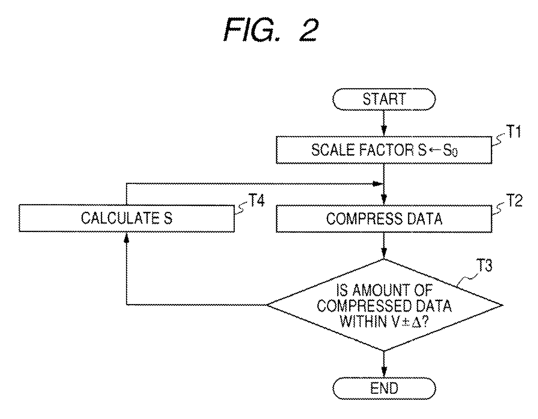
[0037]With reference to FIGS. 1 to 4, a first embodiment of the invention will be described below.

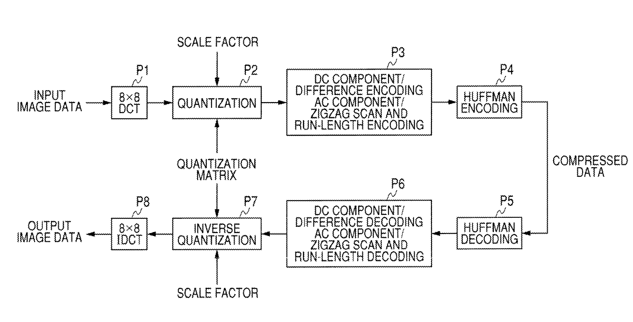
[0038]FIG. 1 is a schematic diagram showing a configuration example of processing steps applying the control over an amount of compressed data according to a first embodiment. In the description, the same reference numerals are given to the same components as those in FIG. 6, which have been described in the example in the past.

[0039]First of all, input image data is divided into multiple blocks each having n×n pixels such as 8×8 pixels horizontally and vertically, and two dimensional discrete cosine transform (DCT) is performed on each of the blocks (process P1).

[0040]The DCT is a kind of orthogonal transform in a frequency region and is defined by:

[0041]F⁡(u,v)=4⁢C⁡(u)⁢C⁡(v)n·n⁢∑i=0n-1⁢∑j=0n-1⁢f⁡(i,j)×cos⁢⁢(2⁢i+1)⁢u⁢⁢π2⁢n⁢cos⁢⁢(2⁢j+1)⁢v⁢⁢π2⁢n(Expression⁢⁢1)

where the conversion coefficient is F(u,v), and the input image data of each one block is f(i,j).

[0042]In⁢⁢this⁢⁢case,C⁡(w)=⁢1 / √2⁢...


PUM


Abstract

An amount-of-compressed-data control method applicable to image data compression processing for compressing an amount of data is disclosed. The method includes the steps of: performing quantization by: dividing one digital image into multiple blocks each having n×n pixels; performing orthogonal transform on each block; and dividing n×n conversion coefficients resulting from the conversion by each threshold value of a quantization matrix including n×n threshold values each resulting from the multiplication of a predetermined coefficient S (where S is a positive real number); and variable-length encoding the quantized data. In this method, the value of the coefficient S allows the amount of compressed data to fit within a predetermined range of a target amount of data by performing the quantization and encoding by dividing the interval that the coefficient S can take on into multiple intervals and calculating the estimated value of the coefficient S based on the relationship between the amount of compressed image data and the coefficient S, which is defined for each of the divided intervals.

Description

CROSS REFERENCES TO RELATED APPLICATIONS[0001]The present invention contains subject matter related to Japanese Patent Applications JP 2006-327159 filed in the Japanese Patent Office on Dec. 4, 2006, the entire contents of which being incorporated herein by reference.BACKGROUND OF THE INVENTION[0002]1. Field of the Invention[0003]The present invention relates to an amount-of-data control method for controlling the compression rate such that the amount of compressed data can be equal to a target amount of data in a case where still image data is to be compressed and transmitted or recorded and to an image data compressing apparatus applying the amount-of-data control.[0004]2. Description of the Related Art[0005]Various standardization methods such as JPEG have been proposed for standardization of still image encoding.[0006]FIG. 6 is a schematic diagram showing processing steps of JPEG. The system divides one input image into multiple blocks each having 8×8 pixels, performs two-dimens...

Claims


Application Information

Patent Timeline
Patent Type & Authority Patents(United States)
IPC IPC(8): G06K9/36H03M7/30H04N1/41H04N19/126H04N19/146H04N19/196H04N19/60H04N19/625H04N19/91
CPCH04N19/176H04N19/149H04N19/192H04N19/60H04N19/126H04N19/15
Inventor IMATA, MASANORIHIROSE, TOSHIHIKOHIRAI, MICHIO
Owner SONY CORP
Learn More