

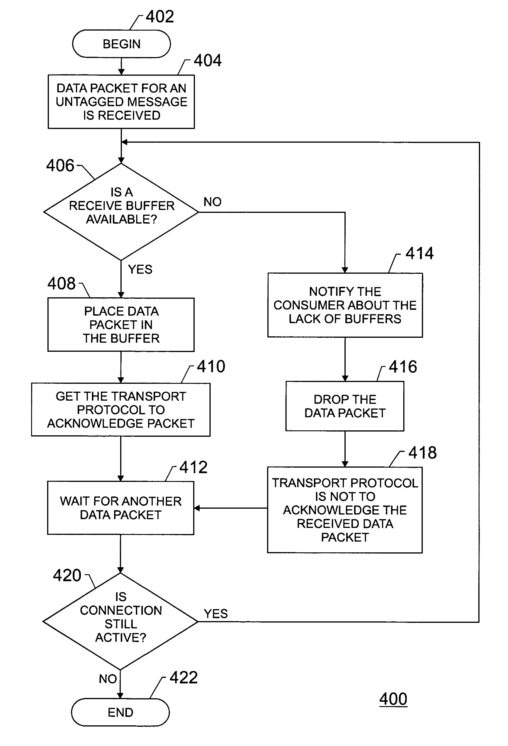
Method and apparatus for handling flow control for a data transfer
a flow control and data transfer technology, applied in the field of methods and, can solve problems such as termination of the connection between the ulps, data transfer may assume that an error has occurred, and loss of data or commands that are being exchanged, and is not an acceptable approach
- Summary
- Abstract
- Description
- Claims
- Application Information
AI Technical Summary
Benefits of technology
Problems solved by technology
Method used
Image

Examples
Embodiment Construction
[0010]One or more specific embodiments of the present invention will be described below. In an effort to provide a concise description of these embodiments, not all features of an actual implementation are described in the specification. It should be appreciated that in the development of any such actual implementation, as in any engineering or design project, numerous implementation-specific decisions may be made to achieve the developers' specific goals, such as compliance with system-related and business-related constraints, which may vary from one implementation to another. Moreover, it should be appreciated that such a development effort might be complex and time consuming, but would nevertheless be a routine undertaking of design, fabrication, and manufacture for those of ordinary skill having the benefit of this disclosure.
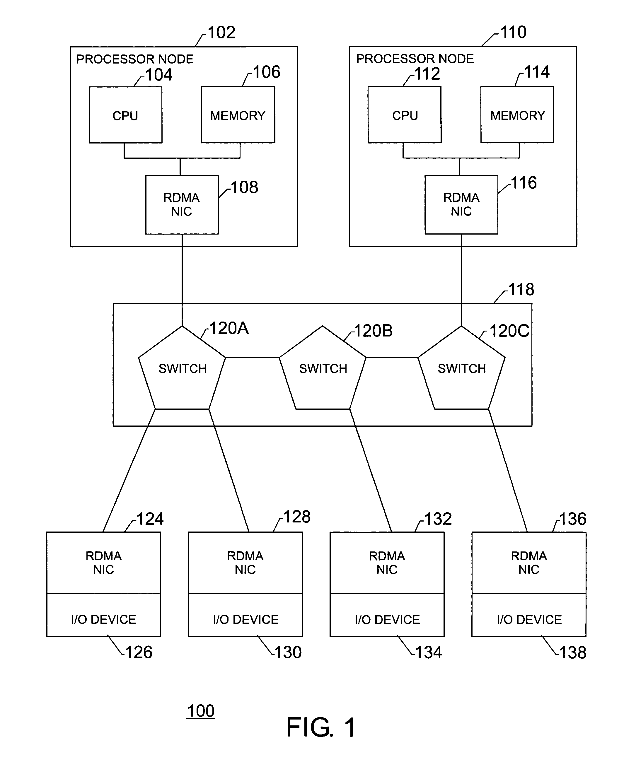
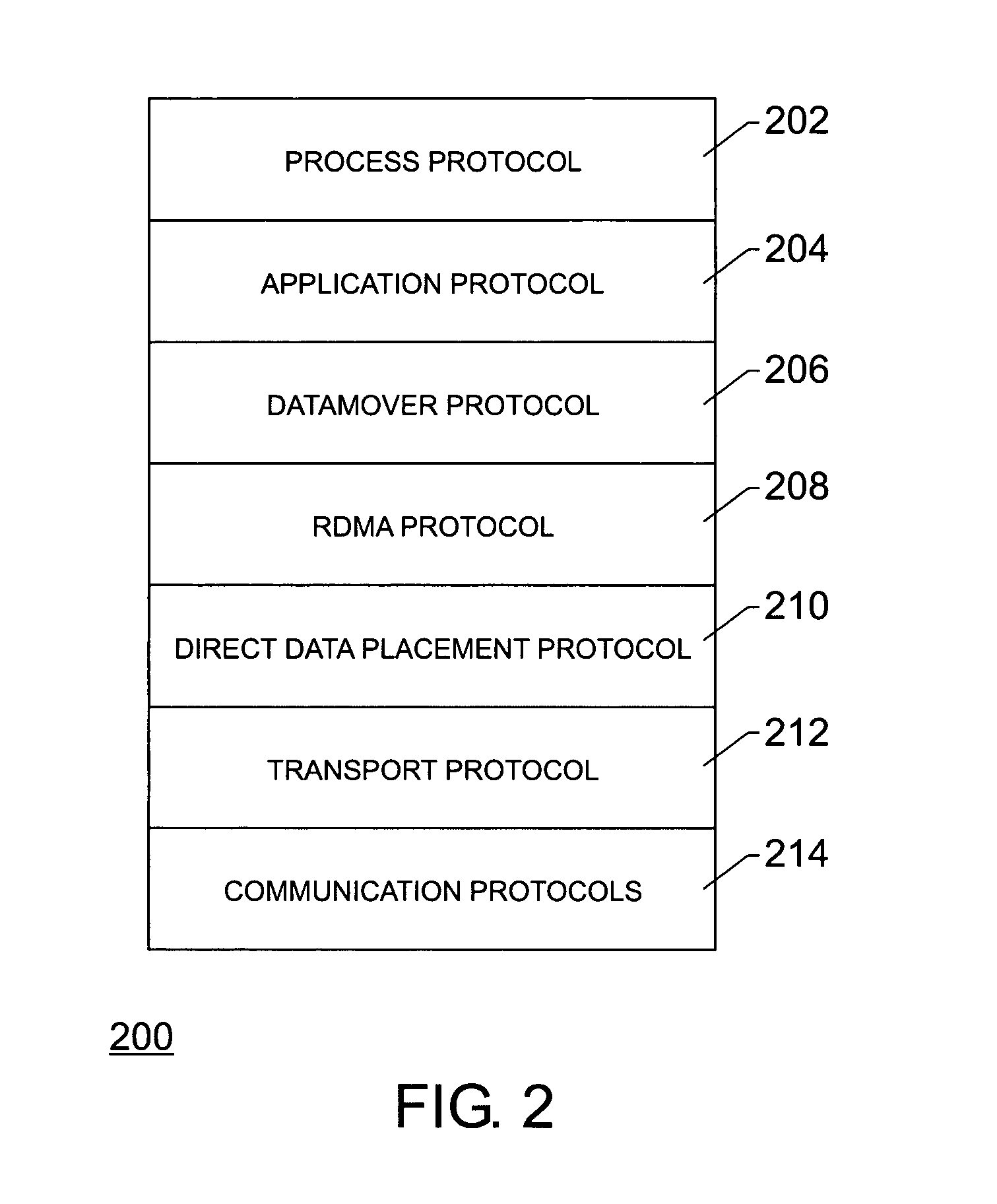
[0011]The Remote Direct Memory Access (“RDMA”) Consortium, which includes the assignee of the present invention, is developing specifications to improve th...
PUM
 Abstract
Description
Claims
Application Information