Gantry loader

a technology of gantry and loader, which is applied in the direction of manufacturing tools, transportation and packaging, and elevated railways, can solve the problems of substantial wear and additional safety risks of supply chains, and achieve the effect of reducing construction costs and flexibly increasing construction efforts

Inactive Publication Date: 2018-11-08
LIEBHERR VERZAHNTECHNIK GMBH
View PDF2 Cites 2 Cited by
  • Summary
  • Abstract
  • Description
  • Claims
  • Application Information

AI Technical Summary

Benefits of technology

[0063]Since an energy supply change is no longer required, the gantry loader can be flexibly equipped with a plurality of carriages. A flexible adaptation to varying production routines is hereby in particular possible without any greater construction effort having to be made. The carriages can furthermore also be replaced without problem and without any great effort for servicing purposes.
[0064]The design of the gantry loader in accordance with the present disclosure has the further advantage that the gantry loader can be extended without problem to adapt it to a varying production process or to new customer demands In the design, only the guide rail has to be correspondingly extended for this purpose and optionally the energy supply sections and / or data transmission sections have to be extended or supplemented by new sections.

Problems solved by technology

Supply chains are, however, exposed to substantial wear due to the movement of the carriage.
There is additionally a safety risk since the supply chain can fall off its support surface.
The implementation of the teaching known from DE 10 2006 049 588 A1 is, however, associated with considerable problems since the contactless transmission of high electrical powers such as is required for the operation of a carriage is associated with great difficulties.

Method used


Image

  • Gantry loader
  • Gantry loader
  • Gantry loader

Examples


first embodiment

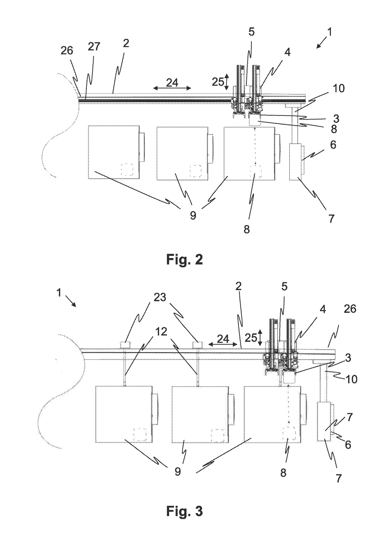
[0099]In the present disclosure that is shown in more detail in FIG. 2, the carriage 1 is supplied with energy in every travel position via the energy supply of the gantry loader. An induction rail 26 is provided for this purpose that extends over the total travel path of the carriage along the guide rail 2. The induction rail 27 can be arranged at the guide rail 2 or at a separate support rail. The induction rail comprises at least one induction loop that cooperates with an induction consumer of the carriage.

[0100]In this embodiment, the energy store 5 of the carriage serves the cushioning of power peaks and therefore the supplementation of the constantly present energy supply by the gantry loader.

[0101]The first embodiment shown in FIG. 2 furthermore comprises a cableless data transmission system that provides a data transmission link between the carriage and the control 6 of the gantry loader in every travel position of the carriage. A data transmission rail 26 can in particular ...

second embodiment

[0104]An energy supply of the carriage in the second embodiment shown in FIGS. 3 and 4 is in contrast provided in specific travel positions and / or travel sections and not provided in other specific travel positions and / or travel sections. Charge units 23 are provided for this purpose that permit an energy supply of the carriage 1 at specific travel positions and / or in specific travel sections. The charge units comprise one or more induction coils that cooperate with one or more induction consumers of the carriage. However, unlike in the embodiment shown in FIG. 2, they no longer extend along the total travel path of the carriage, but are rather provided at points and / or section-wise there.

[0105]As can be seen from FIGS. 3 and 4, the charge units 23 in the embodiment are each provided in a work position of the carriage 1 above a station 9 of the production system. The carriage stops in such work positions to pick up or place down workpieces 8. The charge unit 23 can be utilized durin...

third embodiment

[0109]In the third embodiment shown in FIG. 5, the data transmission also takes place only at points or section-wise. For this purpose, at least one data transmission unit 20 is provided that permits communication with the carriage in specific travel positions and / or in a specific travel section. It is a point-to-point signal exchange in this respect such as industrial Bluetooth.

[0110]In the embodiment, the data transmission units are each arranged at a work position of the carriage 1 above a station 9 of the production system. The data transmission units 20 in the embodiment are furthermore held mechanically via a holder 12 and are electrically coupled to a station 9. The same configurations and alternatives can be used for the mechanical and electrical connection for the data transmission units 20 as for the above-described charge units 23 in accordance with the embodiment in FIGS. 3 and 4.

[0111]If data transmission at points is used, a control 4 of the carriage 1 should be used t...


PUM


Abstract

The present disclosure shows a gantry loader having at least one carriage travelable at a horizontal guide rail, in particular for the transport of workpieces between stations of a production system, wherein the carriage has at least one drive. The present energy is characterized in that the carriage has an energy store for the at least partial energy supply of the drive.

Description

CROSS REFERENCE TO RELATED APPLICATIONS[0001]The present application claims priority to German Patent Application No. 10 2017 109 818.6, entitled “Gantry Loader”, and filed on May 8, 2017. The entire contents of the above-listed application is hereby incorporated by reference for all purposes.TECHNICAL FIELD[0002]The present disclosure relates to a gantry loader having at least one carriage travelable at a horizontal guide rail. Such gantry loaders in particular serve the transport of workpieces between stations of a manufacturing system such as manufacturing machines and / or feed and / or removal devices. Such gantry loaders are sometimes also called gantry robots or overhead transfer devices.BACKGROUND AND SUMMARY[0003]In the mass production of workpieces, in particular in the mechanical manufacture of workpieces, the workpieces are successively fed to a plurality of machine tools in accordance with an exactly planned production routine. For this purpose, the workpieces are first cha...

Claims


Application Information

Patent Timeline
Patent Type & Authority Applications(United States)
IPC IPC(8): B60L5/00B61B3/00B66C19/00B23Q7/04B23Q41/02
CPCB60L5/005B61B3/00B66C19/00B23Q7/04B23Q41/02B23Q5/28B60L2200/26B60L7/10B25J9/0087B25J9/026B25J19/005B60L5/42B60L13/00B60L53/32Y02T10/70Y02T10/7072Y02T90/12
Inventor HAENSCHKE, DAVIDPORSCHE, CHRISTOFMATTERN, THOMAS
Owner LIEBHERR VERZAHNTECHNIK GMBH
Why Eureka
Try Eureka