Muffler device for motorcycle

a muffler and motorcycle technology, applied in the direction of engines, mechanical equipment, machines/engines, etc., can solve the problems of difficult to form a mudguard for the muffler, the muffler shape is limited, and the muffler may be muddied, so as to improve the flexibility of design, facilitate the cutting edge portion of the tail pipe, and improve the effect of design flexibility

Inactive Publication Date: 2012-04-10
HONDA MOTOR CO LTD
View PDF16 Cites 10 Cited by
  • Summary
  • Abstract
  • Description
  • Claims
  • Application Information

AI Technical Summary

Benefits of technology

[0012]Furthermore, since the mud guiding groove is formed as a narrow groove capable of exhibiting capillarity, the mud in the mud guiding groove can be smoothly moved downward around the exhaust outlet by the capillarity. Accordingly, the accumulation of mud on the outer surface of the tail cap around the exhaust outlet can be suppressed.
[0013]According to an embodiment of the invention, the tail pipe supporting member as a small part is formed with the mud guiding groove. Accordingly, the mud guiding groove can be easily formed. Furthermore, in the case of modifying the tail pipe to have different specifications such as changing an outer diameter, it is only necessary to change the design of the tail pipe supporting member. Accordingly, a change in design of the tail cap as a whole can be avoided, thereby improving the flexibility of design.
[0014]According to another embodiment, the tail pipe supporting member is formed with the folded portion, and the cut edge portion of the tail pipe is covered with the folded portion. Accordingly, edge treatment for the cut edge portion of the tail pipe can be facilitated.
[0015]According to an example of the invention, the mud and water in the mud guiding groove can be smoothly dropped through the second mud guiding groove to the ground.

Problems solved by technology

In the case of an off-road vehicle, especially an off-road race vehicle, a large amount of mud is scattered and there is a possibility that a muffler may be muddied.
Further, a muffler shape is limited in such a manner that no projections and depressions must be formed on the muffler due to race strategy and regulation.
Accordingly, it is difficult to form a mudguard for the muffler.

Method used


Image

  • Muffler device for motorcycle
  • Muffler device for motorcycle
  • Muffler device for motorcycle

Examples


Embodiment Construction

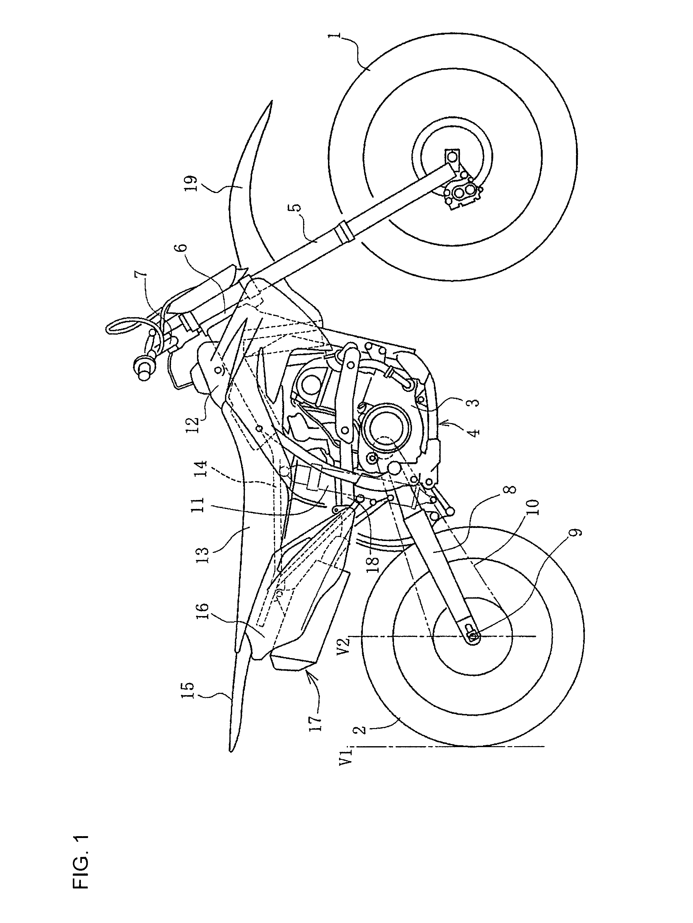
[0025]Some embodiments of the present invention will now be described with reference to the drawings. FIG. 1 is a side view of a racer type motorcycle for a motocross race using a muffler device according to an embodiment of the present invention.

[0026]As shown in the example of FIG. 1, an engine 3 is mounted on a cradle type frame 4 between a front wheel and a rear wheel 2. The front wheel 1 is pivotably supported through a front fork 5 to a head pipe 6 provided at the front end of the frame 4. The front wheel 1 is steered by a steering handle 7. The front fork 5 may be of a telescopic type having a large stroke, thereby ensuring a large stroke of the front wheel 1.

[0027]In one embodiment, a rear swing arm 8 is pivotably supported at its front end to a rear portion of the frame 4. The rear wheel 2 is supported through an axle 9 to the rear end of the rear swing arm 8. The rear wheel 2 is driven by a chain 10. A rear cushion unit 11 may be provided between the rear swing arm 8 and a...


PUM


Abstract

An exhaust outlet 34 is formed at the center of a rear end wall 46 of a tail cap 21 closing a rear end opening of a muffler body 20, and a tail pipe 30 is connected at its rear end to the exhaust outlet 34. The exhaust outlet 34 is formed through a tail pipe supporting member 35 mounted on the rear end wall 46. The tail pipe supporting member 35 is formed with an annular mud guiding groove 37 opening rearward around the exhaust outlet 34. The mud accumulated on the rear end wall 46 is guided into the mud guiding groove 37 and moved in the mud guiding groove 37 owing to its capillarity. Accordingly, the mud can be moved down along the mud guiding groove 37 and smoothly dropped to the ground, thus preventing the clogging of the exhaust outlet 34 with the mud on the rear end wall 46.

Description

BACKGROUND[0001]1. Field[0002]Embodiments of the present invention relate to a muffler device for a motorcycle suitable for running on a muddy road, such as for a motocross race.[0003]2. Description of the Related Art[0004]Conventionally known is a muffler device for a motorcycle including an outer pipe connected to the rear end of an exhaust pipe, a conical tail cap closing a rear end opening of the outer pipe, and a tail pipe having a rear end exposed to an exhaust outlet formed through the tail cap (see Japanese Utility Model Publication No. Sho 59-10338).[0005]In the case of an off-road vehicle, especially an off-road race vehicle, a large amount of mud is scattered and there is a possibility that a muffler may be muddied. Further, a muffler shape is limited in such a manner that no projections and depressions must be formed on the muffler due to race strategy and regulation. Accordingly, it is difficult to form a mudguard for the muffler.[0006]Further, in the case that the rear...

Claims


Application Information

Patent Timeline
Patent Type & Authority Patents(United States)
IPC IPC(8): F01N13/00
CPCF01N13/08F01N13/082F01N13/1838F01N2590/04
Inventor INOUE, YUSUKE
Owner HONDA MOTOR CO LTD
Why Eureka
Try Eureka