Peripheral discharge tube axial fan

a technology of axial fans and axial tubes, which is applied in the direction of wind motors with perpendicular air flow, waterborne vessels, machines/engines, etc., can solve the problems of reducing the efficiency of axial fans, prone to overloading, and not providing the high flow rate of axial tube fans, so as to achieve the effect of increasing the radial airflow

Active Publication Date: 2012-04-10
AMETEK INC
View PDF15 Cites 70 Cited by
  • Summary
  • Abstract
  • Description
  • Claims
  • Application Information

AI Technical Summary

Benefits of technology

[0007]It is another aspect of the present invention to provide a cooling fan assembly comprising a hub carrying an electric motor, the hub having an axis of rotation extending therethrough, a plurality of fan blades spaced circumferentially around the hub, an annular venturi radially surrounding the fan blades, and at least one slot in the venturi to allow air to flow radially through the venturi, wherein rotation of the fan blades caused by the electric motor generates axial airflow through the annular venturi and radial airflow through the at least one slot, and wherein the radial airflow increases as the axial airflow decreases to provide a substantially consistent flow of cooling air.

Problems solved by technology

At higher pressures, such as in compact electrical devices where components may block axial airflow, tube axial fans decrease in efficiency and are prone to overloading.
While centrifugal fans can operate at high pressures and can avoid over-loading, they do not provide the high flow rate that axial tube fans can provide.
In many modern devices, size is a significant concern.
The high density of heat generating electronics within these devices and the lack of space for air flow can create unique cooling demands.

Method used


Image

  • Peripheral discharge tube axial fan
  • Peripheral discharge tube axial fan
  • Peripheral discharge tube axial fan

Examples


Embodiment Construction

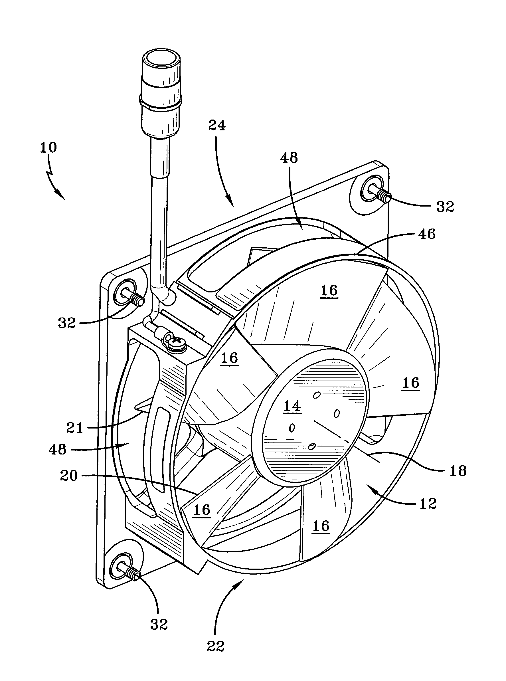
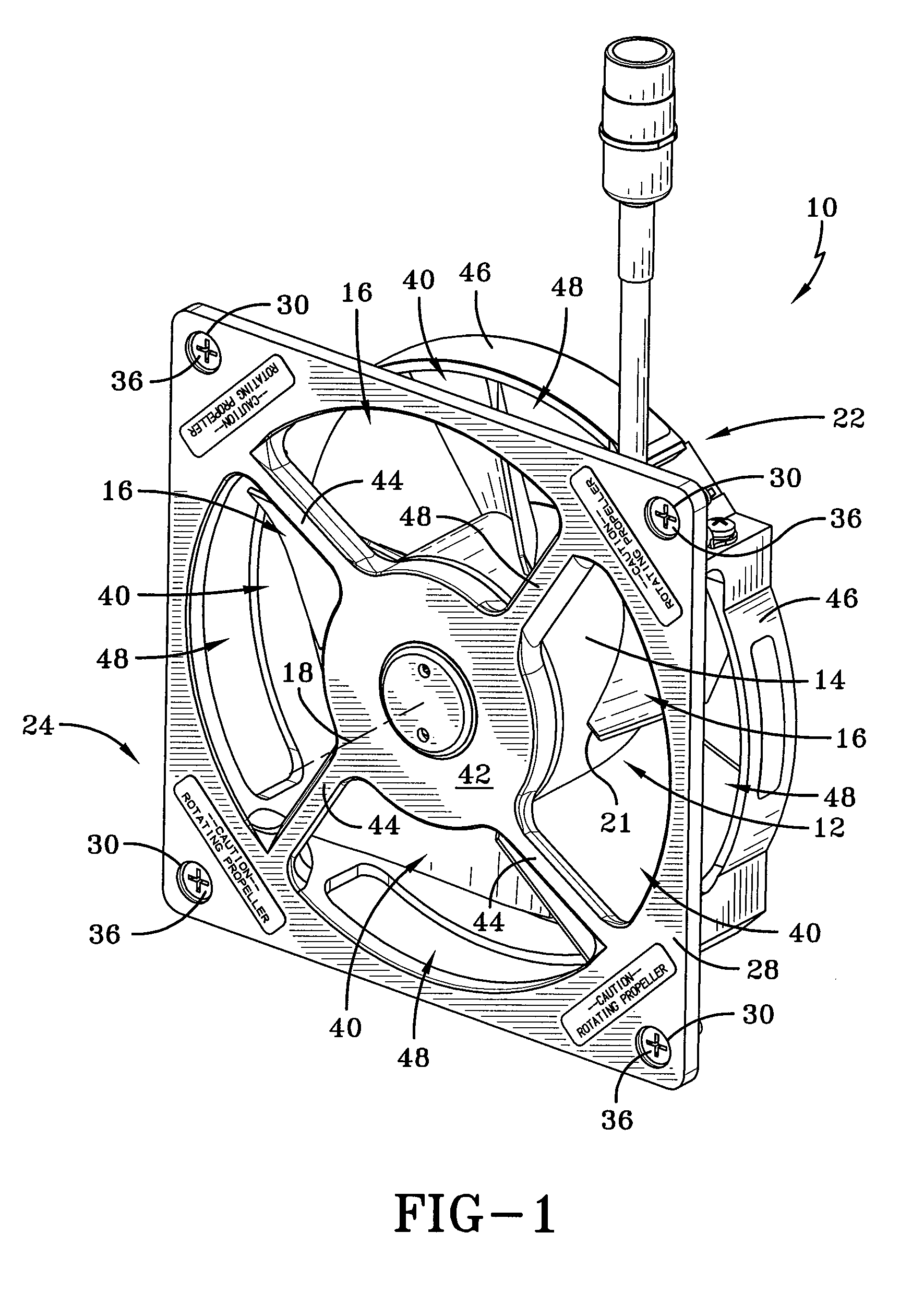
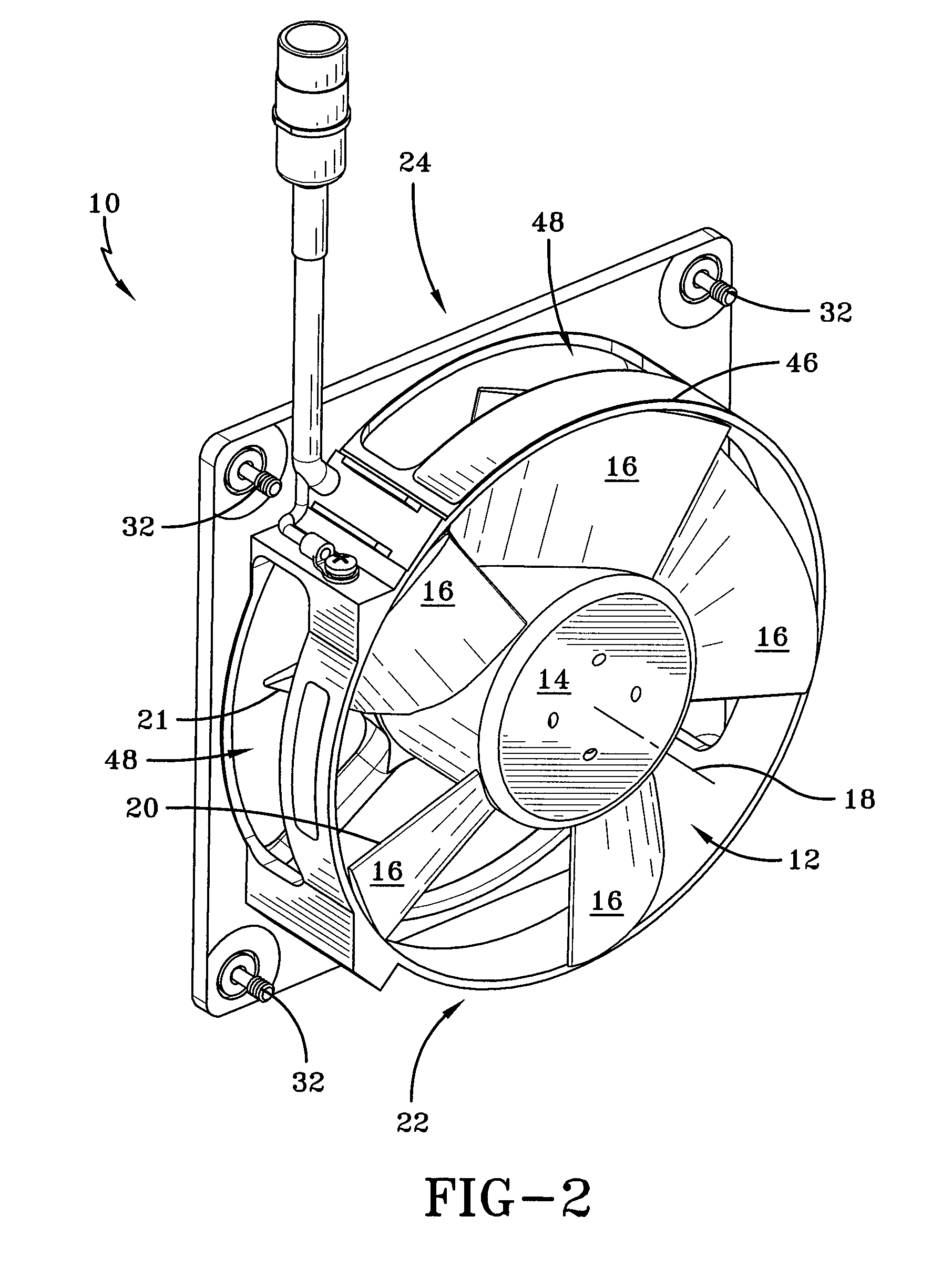
[0018]An exemplary fan assembly according to the concepts of the present invention is generally indicated by the numeral 10 in the drawings. Fan assembly 10 may be installed in an electronic device as a cooling fan, and may be strategically placed in order to maximize airflow across specific heat-generating components, or heat sinks, within the device. The assembly may be installed and positioned so as to draw cooling air into the device, or may be installed and positioned to exhaust hot air from the device. Some devices may utilize multiple fan assemblies to both draw cooling air into the device and exhaust hot air from the device.

[0019]Fan assembly 10 includes an impeller 12 having a hub 14 at its center and a plurality of fan blades 16 spaced circumferentially around and extending radially from hub 14. Hub 14 is generally cylindrical in shape, and encloses an electric motor (not shown) therein, as is well known in the art. The electric motor may be either a DC motor or an AC moto...


PUM


Abstract

A mixed flow fan assembly includes an electric motor, an impeller having a hub enclosing the motor, and a plurality of fan blades spaced circumferentially around the hub. The fan assembly also includes an axis of rotation extending through the hub, an annular venturi radially surrounding the impeller, and a mounting plate with an opening to allow for axial airflow positioned on one open end of the venturi. The venturi has at least one elongated slot to allow for radial airflow from the fan assembly, the slot being oriented substantially perpendicular to the axis of rotation and having a generally rectangular shape. Rotation of the hub and the fan blades caused by the electric motor generates both axial and radial airflow through the fan assembly.

Description

TECHNICAL FIELD[0001]One or more embodiments of the present invention relate to a cooling fan assembly for use in electronic devices. Specifically, one or more embodiments of the present invention relate to a cooling fan assembly adapted to generate both axial and radial airflow.BACKGROUND ART[0002]A wide variety of electronic devices and systems employ cooling fans in their housings. The cooling fans generate air flow through the housing and across or over heat generating components to prevent overheating and to protect the heat generating components from damage resulting from extreme temperatures. Devices that conventionally use cooling fans include, for example, portable and desktop computers, radios, automobiles, industrial equipment, and communication system infrastructure. Cooling fans typically come in one of two forms: tube axial fans and motorized impeller fans, otherwise known as centrifugal flow fans.[0003]Tube axial fans have blades that force air to move parallel to the...

Claims


Application Information

Patent Timeline
Patent Type & Authority Patents(United States)
IPC IPC(8): F04D25/06F04D29/34
CPCF04D25/08F04D29/526F04D25/0613
Inventor BOGGESS, JR., ANDREW LACEYLEVIN, GENNADY M.
Owner AMETEK INC
Why Eureka
Try Eureka