
Single clutch, two planetary hybrid architecture

a hybrid architecture and clutch technology, applied in hybrid vehicles, gearing, electric propulsion mounting, etc., can solve the problems of hydraulic system cost and packaging problems, and achieve the effects of reducing the number of required components, reducing the overall cost, and good driving range and fuel economy

Active Publication Date: 2012-04-10
GM GLOBAL TECH OPERATIONS LLC
View PDF11 Cites 6 Cited by
  • Summary
  • Abstract
  • Description
  • Claims
  • Application Information

AI Technical Summary

Benefits of technology

[0003]Existing hybrid architectures provide good driving range and fuel economy, but require multiple clutches to establish the various operating modes, and hence present packaging issues in smaller vehicles, as well as cost issues associated with the hydraulic system required to operate the clutches. There is a need for hybrid powertrains that offer the fuel economy benefits of various operating modes while containing overall cost by minimizing the number of required components and / or by providing design flexibility for a variety of vehicle platforms by scaling component size or capacity as required for a particular platform.
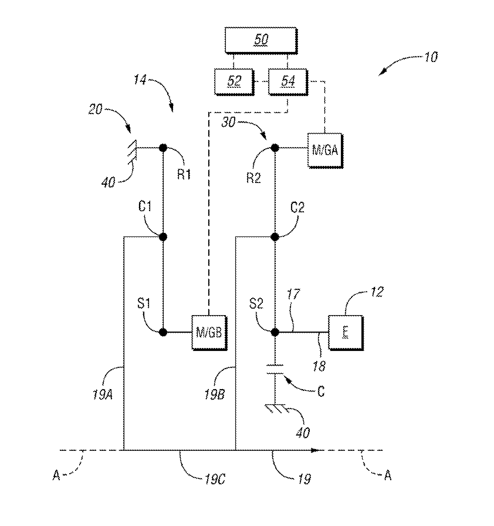
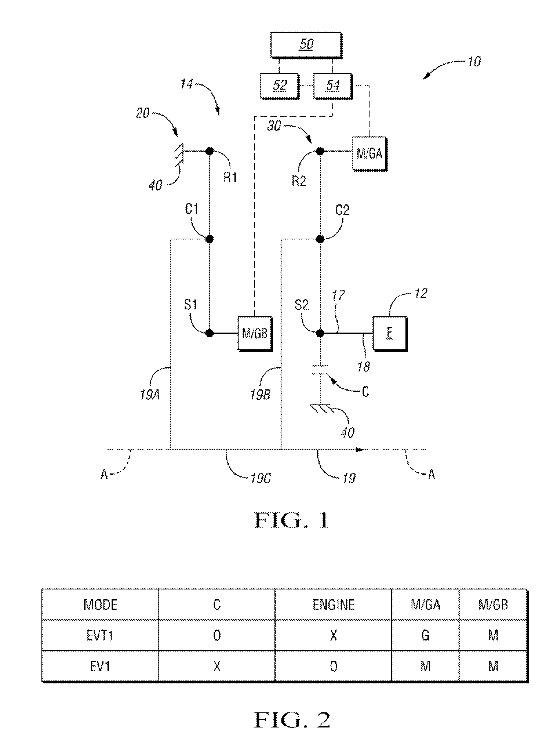
[0004]The powertrain architecture provided has only one clutch, hence reducing or completely eliminating hydraulics and the associated cost and packaging space requirements. Specifically, a hybrid powertrain for a vehicle includes a prime mover, which may be an engine, and a transmission that has an input member configured for connection with the prime mover to receive torque from the prime mover, an output member, and a stationary member. A first motor / generator and a second motor / generator are provided as additional motive sources. A first planetary gear set and a second planetary gear set are included, each having a respective first member, second member, and third member. The input member and the engine are continuously connected for common rotation with the first member of the second planetary gear set. The second motor / generator is connected for rotation with the second member of the second planetary gear set. The first motor / generator is connected for common rotation with the first member of the first planetary gear set. The second member of the first planetary gear set is continuously grounded to the stationary member. The third member of the first planetary gear set and the third member of the second planetary gear set are connected for common rotation with the output member. Only one clutch is operatively connected to the transmission, and it is selectively engagable to ground the input member and the first member of the second planetary gear set to the stationary member.
[0005]In at least one embodiment, the clutch is an electromagnetic clutch, and thus does not require any pressurized hydraulic fluid for engagement. In comparison with a hydraulic clutch, an electromagnetic clutch facilitates packaging, and may reduce weight, cost, and clutch response time. The member that the engine is connected to may be a sun gear member, thus allowing torque multiplication through the planetary gear sets so that the engine may operate closer to its most efficient operating speed. Because both motor / generators are operatively connected with the transmission output member, if one motor / generator fails, the other can still be operated as a motor or a generator to allow hybrid operating modes.
[0006]The powertrain is sufficiently compact such it can be easily embedded in existing manual transmissions and automatic transmissions. In a manual transmission, the clutch could be driver operated. The powertrain can realize improved or comparable fuel economy to that of existing two motor architectures.

Problems solved by technology

Existing hybrid architectures provide good driving range and fuel economy, but require multiple clutches to establish the various operating modes, and hence present packaging issues in smaller vehicles, as well as cost issues associated with the hydraulic system required to operate the clutches.

Method used


Image

  • Single clutch, two planetary hybrid architecture
  • Single clutch, two planetary hybrid architecture

Examples


Embodiment Construction

[0010]Referring to the drawings, FIG. 1 shows a hybrid powertrain 10 that includes a prime mover, such as an internal combustion engine 12 (labeled E), connected with a hybrid transmission 14. Other types of prime movers, such as fuel cells, pneumatic engines, etc. may be used in place of an internal combustion engine. The hybrid transmission 14 includes two additional motive sources, a first motor / generator M / GB and a second motor generator M / GA. The engine E and motor / generators M / GA and M / GB are interconnected via two planetary gear sets 20 and 30 to provide various operating modes.

[0011]A first planetary gear set 20 includes a sun gear member 51, a ring gear member R1, and a carrier member C1 that rotatably supports a set of pinions that mesh with both the sun gear member S1 and the ring gear member R1. The sun gear member S1 is referred to as the first member of the planetary gear set 20. The ring gear member R1 is referred to as the second member of the planetary gear set 20. ...


PUM


Abstract

A hybrid powertrain for a vehicle includes a prime mover, which may be an engine, and a transmission that has an input member configured for connection with the prime mover to receive torque from the prime mover, an output member, and a stationary member. A first motor / generator and a second motor / generator are provided as additional motive sources. A first planetary gear set and a second planetary gear set are included, each having a respective first member, second member, and third member. Only one clutch is operatively connected to the transmission, and it is selectively engagable to ground the input member and the first member of the second planetary gear set to the stationary member.

Description

TECHNICAL FIELD[0001]The invention relates to a hybrid transmission having two motor / generators, only two planetary gear sets, and a single torque-transmitting mechanism.BACKGROUND OF THE INVENTION[0002]Automotive hybrid powertrains typically have an engine and one or more motor / generators interconnected by transmission gearing and selectively engagable torque-transmitting mechanisms controlled to provide various vehicle operating modes, such as one or more electrically-variable modes of operation, fixed speed ratio modes, and an electric-only (battery-powered) mode. Hybrid powertrains may improve vehicle fuel economy in a variety of ways, primarily by using one or both of the motor / generators for vehicle braking and using the regenerated energy to power the vehicle electrically, with the engine off. The engine may be turned off at idle, during periods of deceleration and braking, and during periods of low speed or light load operation to eliminate efficiency losses due to engine dr...

Claims


Application Information

Patent Timeline
Patent Type & Authority Patents(United States)
IPC IPC(8): F16H3/72B60K1/00F16H37/06
CPCB60K6/445B60K2006/381Y10T477/26Y02T10/6239F16H2037/0866Y02T10/62
Inventor TIWARI, AWADESHGV, RAVIKANTHRAVICHANDRAN, SRIRAMNAIDU, KUMPATLA VVP
Owner GM GLOBAL TECH OPERATIONS LLC
Learn More