Eureka AIR delivers breakthrough ideas for toughest innovation challenges, trusted by R&D personnel around the world.

Method of heating superposed components and heating apparatus therefor

Inactive Publication Date: 2012-04-10
FUJITSU LTD
View PDF17 Cites 0 Cited by
  • Summary
  • Abstract
  • Description
  • Claims
  • Application Information

AI Technical Summary

Benefits of technology

[0006]It is accordingly an object of the present invention to provide a method of heating superposed components contributing to reduction in production cost and improvement in productivity, reliably avoiding a relative displacement or slippage between first and second components. In addition, it is another object of the present invention to provide a heating apparatus contributing to realization of the aforementioned method.
[0007]According to a first aspect of the present invention, there is provided a method of heating superposed components, comprising: setting a plurality of first components on a work stage, said first components commonly connected to a first connection member; superposing a plurality of second components on the first components, said second components commonly connected to a second connection member; and subjecting heat from the second components, preventing the first and second connection members from thermal expansion.
[0008]This method allows the first components as well as the second components to be handled as a one-piece component. Accordingly, the first and second components can be subjected to superposition and heating in a facilitated manner, as compared with the case where each component is separately handled. It leads to an improved productivity. In addition, the first and second connection members are prevented from thermal expansion during heating. The constant intervals are reliably maintained between the adjacent first components and the adjacent second components. The first and second components can in this manner be prevented from a relative displacement or slippage.

Problems solved by technology

An expensive image recognition technique and an expensive positioning robot are required to achieve the accurate positioning of the microcomponent and the electrode plate.

Method used


Image

  • Method of heating superposed components and heating apparatus therefor
  • Method of heating superposed components and heating apparatus therefor
  • Method of heating superposed components and heating apparatus therefor

Examples


Embodiment Construction

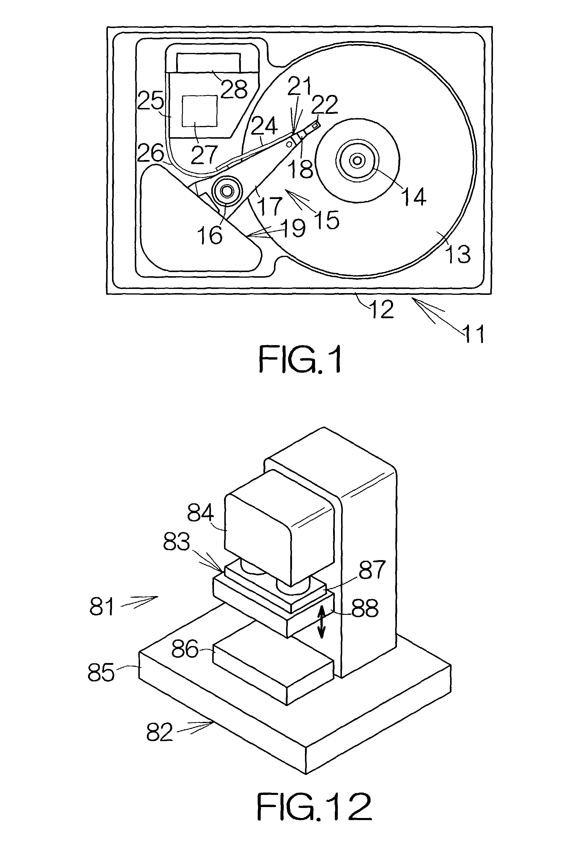
[0049]FIG. 1 schematically illustrates the inner structure of a hard disk drive (HDD) 11 as an example of a recording medium drive or storage device. The HDD 11 includes a box-shaped primary enclosure 12 defining an inner space of a flat parallelepiped, for example. At least one magnetic recording disk 13 is accommodated in the inner space within the primary enclosure 12. The magnetic recording disk 13 is mounted on a driving shaft of a spindle motor 14. The spindle motor 14 is allowed to drive the magnetic recording disk 13 for rotation at a higher revolution speed such as 7,200 rpm or 10,000 rpm, for example. A cover, not shown, is coupled to the primary enclosure 12 so as to define the closed inner space between the primary enclosure 12 and the cover itself.

[0050]A head assembly 15 is also accommodated in the inner space of the primary enclosure 12. The head assembly 15 is coupled to a vertical support shaft 16 for relative rotation. The head assembly 15 includes actuator arms 17...


PUM


Abstract

A first plate material is set on a work stage. The first plate material includes first components commonly connected to a first connection member. A second plate material is subsequently set on the work stage. The second plate material includes second components commonly connected to a second connection member. The second components are superposed on the corresponding first components. The first components as well as the second components can be handled as a one-piece component. It leads to an improved productivity. Heat surfaces of a heat block contact the second components. The connection members are prevented from thermal expansion. The constant intervals are reliably maintained between the adjacent first components and the adjacent second components.

Description

BACKGROUND OF THE INVENTION[0001]1. Field of the Invention[0002]The present invention relates to a method of heating superposed components, comprising superposing first and second components on a work stage, and allowing a heat block to contact with at least the second component so as to heat the first and second components. In particular, the invention relates to a heating apparatus utilized in the same method.[0003]2. Description of the Prior Art[0004]As conventionally known, a piezoelectric microactuator sometimes includes a pair of sheared piezoelectric elements. The piezoelectric elements in the form of a plate is interposed between a pair of electrode plates in the piezoelectric microactuator of this type. The electrode plates are individually adhered to the front and back surfaces of the piezoelectric element. A stationary microcomponent is adhered to one of the electrode plates, while a movable microcomponent is adhered to the other of the electrode plates. A thermosetting a...

Claims


Application Information

Patent Timeline
IPC IPC(8): H05B3/10H05B3/02B81C99/00G11B21/21H01L41/22H01L41/313H02N2/00
CPCH01L41/313H10N30/073
Inventor FUJII, MASANAOOKADA, TORUKOBAYASHI, HIDEHIKOSHIMOURA, SEIICHI
Owner FUJITSU LTD
Why Eureka
Eureka Blog
Learn More