
Image coding apparatus and method

a coding apparatus and image technology, applied in the field of image coding apparatus and image coding method, can solve the problems of difficult to quickly start decoding from the picture, the amount of data contained in digitized moving images is huge, and the coding efficiency of coding efficiency is deteriorating, so as to improve the arbitrariness of random access to a target scene, without deteriorating the coding efficiency

Inactive Publication Date: 2012-04-10
CANON KK
View PDF9 Cites 2 Cited by
  • Summary
  • Abstract
  • Description
  • Claims
  • Application Information

AI Technical Summary

Benefits of technology

The present invention provides an image coding apparatus and method that allows for random access to the middle of an image stream without affecting coding efficiency. Additionally, the invention improves the flexibility in accessing specific scenes within an image stream. The apparatus and method set a first coding picture and a second coding picture during coding processing, with the second coding picture being proximate to the first coding picture. This allows for efficient compression and coding of image data. The invention also provides a computer-readable medium containing instructions for performing the coding steps described above.

Problems solved by technology

The amount of data contained in digitized moving images is huge.
However, due to such flexible reference being allowed, rapid random access may not be achieved.
Thus, it is difficult to quickly start decoding from the picture I5.
However, since the amount of generated code for an IDR picture to be coded using information within the picture is large, setting a large number of pictures as IDR pictures may deteriorate coding efficiency.
In addition, if many IDR pictures are used, the originally provided flexible reference relationship in the H.264 coding method may be restricted.
Thus, the efficiency of inter-picture coding may also be deteriorated.
Thus, coding efficiency is deteriorated.

Method used


Image

  • Image coding apparatus and method
  • Image coding apparatus and method
  • Image coding apparatus and method

Examples


first exemplary embodiment

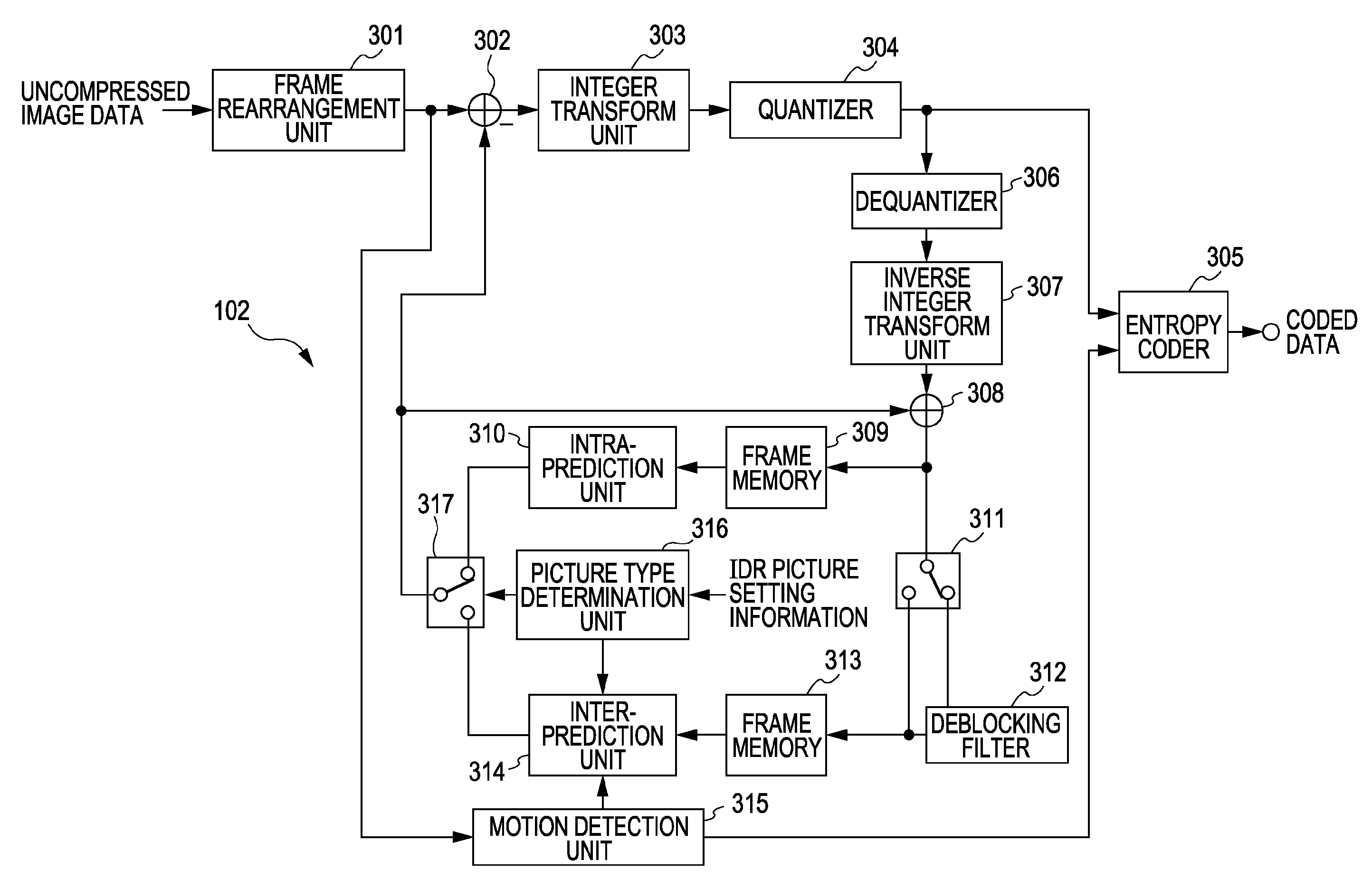
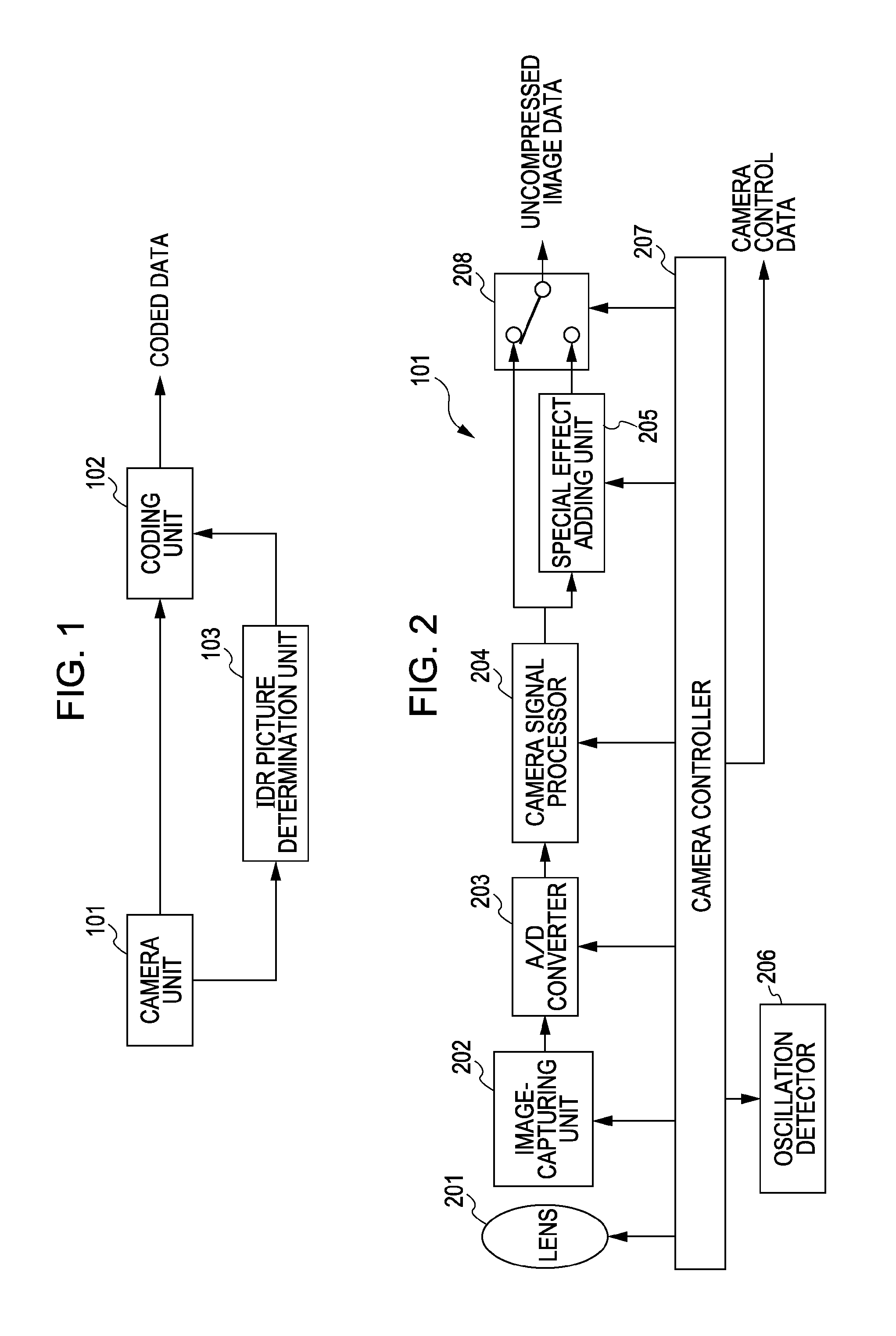
[0047]A first exemplary embodiment of the present invention will now herein be described. FIG. 1 is a block diagram showing the configuration of an image coding apparatus according to the first embodiment of the present invention. Such an image coding apparatus is applicable to a digital camera, a digital video camera (camcorder), or a captured image coding system that is configured by connecting a camera to a coding apparatus (a personal computer or the like).

[0048]The image coding apparatus according to the first embodiment sets an IDR picture at a scene to which a higher attention is paid by a viewer in accordance with camera control data, and sets a conditional P picture on which a motion reference relationship is restricted (hereinafter, also referred to as a conditional P picture) that enables random access in conjunction with the setting of the IDR picture. The conditional P picture on which the motion reference relationship is restricted will be explained later.

[0049]Referri...

second exemplary embodiment

[0100]A second embodiment of the present invention will now be described. FIG. 17 is a block diagram showing the configuration of an image coding apparatus according to the second embodiment. The image coding apparatus according to the second embodiment is capable of setting a conditional P picture in conjunction with an IDR picture set in response to a scene change. Since parts referred to with the same reference numerals as in the first embodiment perform similar operations and processing, the descriptions of those same parts will not be repeated here.

[0101]A scene change detection unit 1701 detects a scene change, for example, when the difference in pixel values between frames of uncompressed image data output from the camera unit 101 is larger than a predetermined threshold value. When detecting a scene change, the scene change detection unit 1701 outputs IDR picture setting information. Then, the picture type determination unit 316 sets a picture type as an IDR picture. For exa...


PUM


Abstract

An image coding apparatus includes a coding unit configured to set, when coding processing is performed on input image data, a first coding picture that is to be generated by intra-picture prediction coding within the first coding picture, skip reference beyond the first coding picture being inhibited, and set, when coding processing is performed on the input image data, a second coding picture that is to be generated by inter-picture prediction coding, and skip reference beyond the second coding picture being inhibited. The coding unit performs coding processing on the input image data such that at least one second coding picture is set proximate to the first coding picture.

Description

BACKGROUND OF THE INVENTION[0001]1. Field of the Invention[0002]The present invention relates to an image coding apparatus and an image coding method that perform inter-prediction between pictures to compress and code input images.[0003]2. Description of the Related Art[0004]As technologies for coding images with high efficiency, coding methods, such as the Joint Photographic Experts Group (JPEG) method and the Moving Picture Experts Group (MPEG) 1 and 2 methods using motion prediction and motion compensation, have been established. Manufacturers have been developing and manufacturing image-capturing apparatuses, such as digital cameras and video cameras, and digital versatile disc (DVD) recorders that are capable of recording images using such coding methods. In addition to these apparatuses, users have been able to easily view recorded images using personal computers or DVD players.[0005]The amount of data contained in digitized moving images is huge. Thus, moving image coding met...

Claims


Application Information

Patent Timeline
Patent Type & Authority Patents(United States)
IPC IPC(8): H04N7/12G06K9/36
CPCH04N5/232H04N19/142H04N19/107H04N19/61H04N23/67
Inventor KOBAYASHI, SATORU
Owner CANON KK
Learn More