Power transmission device

a technology of transmission device and electric motor, which is applied in the direction of interengaging clutch, vehicle sub-unit features, gearing, etc., can solve the problems of deteriorating efficiency in travelling using the electric motor only, insufficient rotational speed of the electric motor, etc., and achieve the effect of preventing the deterioration of efficiency due to companion turning of the electric motor

Active Publication Date: 2017-05-25
HONDA MOTOR CO LTD
View PDF1 Cites 2 Cited by
  • Summary
  • Abstract
  • Description
  • Claims
  • Application Information

AI Technical Summary

Benefits of technology

The present invention provides a power transmission device that can use a conventional transmission as it is, without deteriorating efficiency in using an electric motor only. This is achieved by configuring the device to bring the switching mechanism into a neutral state when the vehicle travels using the electric motor only, preventing deterioration in efficiency due to companion turning by the electric motor.

Problems solved by technology

Here, when the travel speed of the hybrid vehicle is excessively low, the rotational speed of the electric motor may be insufficient to reach a startable rotational speed at which the internal combustion engine can be started.
However, in a conventional transmission, an adjustment part which adjusts a transmission amount is not intended to adjust a transmission amount of driving power required for starting.
In this case, however, an electric motor is always associated with the internal combustion engine while travelling using only the electric motor, and thus, efficiency in travelling using the electric motor only is deteriorated.

Method used


Image

  • Power transmission device
  • Power transmission device
  • Power transmission device

Examples


first embodiment

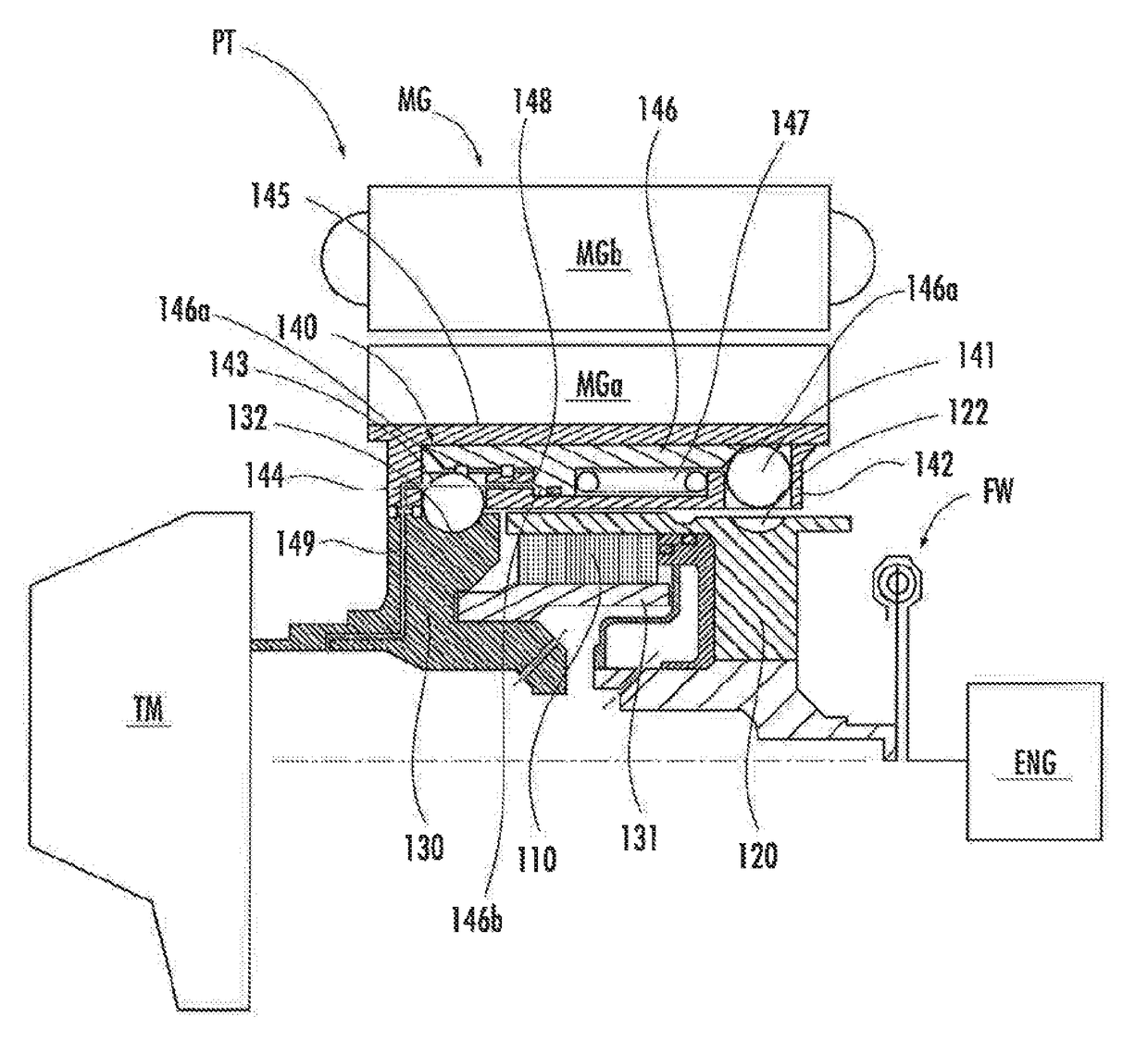
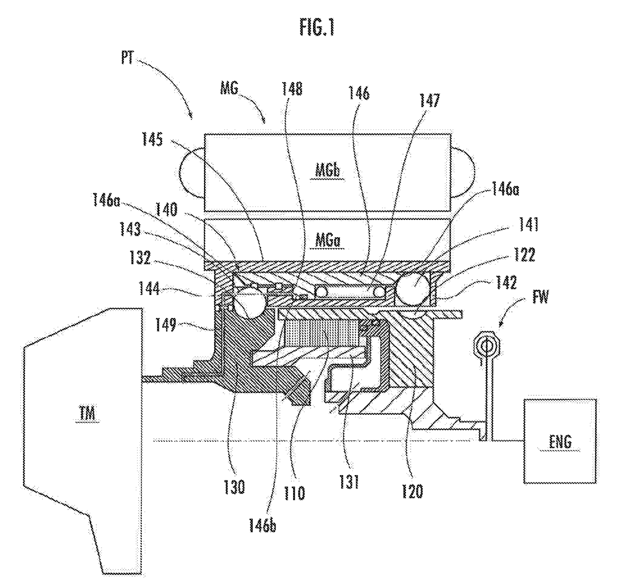
[0034]As illustrated in FIG. 1, a power transmission device PT of a first embodiment of the present invention transmits power of an internal combustion engine ENG to a transmission TM in a releasable manner, and includes an electric motor MG that has a rotor MGa and a stator MGb and that is capable of generating power. In FIG. 1, the power transmission device PT is illustrated in larger size than the internal combustion engine ENG and the transmission TM, and only a part thereof above a rotational axis line indicated by an alternate long and short dash line is illustrated.

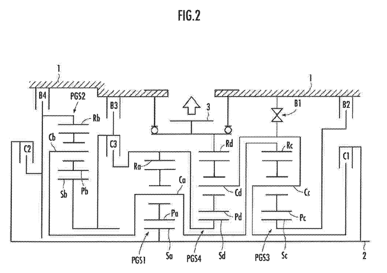
[0035]FIG. 2 illustrates the automatic transmission TM of the first embodiment, The automatic transmission TM includes an input shaft 2 as an input part which is rotatably supported in a casing 1, and to which driving power outputted from a dual mass flywheel FW by the internal combustion engine ENG is transmitted via the power transmission device PT, and an output part 3 which is formed of an output gear arranged ...

second embodiment

[0119]A power transmission device PT of the second embodiment of the present invention is described with reference to FIGS. 10 to 12. Components same as those in the first embodiment are represented by the same reference characters and explanations thereof are omitted.

[0120]The cylindrical slider 146 of the second embodiment has transmission side internal teeth 146c arranged at the transmission TM side end of the inner circumferential surface of the slider 146 and internal combustion engine side internal teeth 146d arranged at the internal combustion engine ENG side end of the inner circumferential surface of the slider 146.

[0121]The transmission side internal teeth 146c each have lateral surfaces 146e having a V shape pointed to the transmission TM side. The internal combustion engine side internal teeth 146d each have lateral surfaces 146f having a V shape pointed to the internal combustion engine side.

[0122]Output side external teeth 123 are provided an the outer circumferential ...


PUM


Abstract

A power transmission device PT includes a clutch input part 120, a clutch output part 130, a start clutch 110 which can connect the clutch input part 120 and the clutch output part 130 to each other, and an electric motor MG having a rotor MGa. The clutch input part 120, the clutch output part 130, and the start clutch 110 are arranged in the rotor MGa. The power transmission device PT includes a switching mechanism 140 which is switchable between an output side correction state in which the rotor MGa and the clutch output part 130 are connected to each other and an input side connection state in which the rotor MGa and the clutch input part 120 are connected to each other.

Description

FIELD OF THE INVENTION[0001]The resent invention relates to a power transmission device used for a vehicle which travels using power from an internal combustion engine and an electric motor.Description of the Related ArtBACKGROUND OF THE INVENTION[0002]Power transmission devices have been conventionally known which are used. for vehicles which each include a wet start clutch and travel using power from an internal combustion engine and an electric motor (for example, see Japanese Patent Laid-Open No. 2010-516558).[0003]When a transmission with a torque converter which enables travelling using only an internal combustion engine as a motor is modified to a transmission for a hybrid vehicle, an electric motor may be arranged in place of the torque converter. This enables the existing transmission to be used as a transmission for a hybrid vehicle without replacing the transmission.[0004]While travelling using an electric motor, a hybrid vehicle starts an internal combustion engine, if n...

Claims


Application Information

Patent Timeline
Patent Type & Authority Applications(United States)
IPC IPC(8): B60K6/387F16D41/066B60L50/16
CPCB60K6/387F16D2041/0601B60Y2200/92B60Y2400/421Y10S903/914Y10S903/911Y10S903/919B60K6/365B60K6/547B60Y2400/73F16H3/66F16H2200/0069F16H2200/2012F16H2200/2046F16H2200/2066F16H2200/2082F16D41/066B60K6/24B60K6/26B60K6/40B60K6/48B60K2006/4825F16D11/14F16D11/16F16D25/0638F16D41/105F16D2011/004H02K7/006H02K7/108Y02T10/62
Inventor IZUMI, MASAO
Owner HONDA MOTOR CO LTD
Why Eureka
Try Eureka