Switched reluctance motor system, and method of controlling switched reluctance motor system

a technology of switched reluctance and motor system, which is applied in the direction of control system, synchronous motor, electrical apparatus, etc., can solve problems such as efficiency degradation, and achieve the effect of reducing vibration and noise, without deteriorating the efficiency of the switched reluctance motor

Active Publication Date: 2019-11-19
TOYOTA JIDOSHA KK +1
View PDF14 Cites 0 Cited by
  • Summary
  • Abstract
  • Description
  • Claims
  • Application Information

AI Technical Summary

Benefits of technology

[0007]This disclosure makes it possible to reduce vibration and noise, without deteriorating the efficiency of a switched reluctance motor.
[0024]With the disclosure, it is possible to reduce vibration and noise, without deteriorating the efficiency of the switched reluctance motor.

Problems solved by technology

Therefore, the efficiency may be deteriorated if the NSNNSN windings are employed only in view of improvement of the maximum torque.

Method used


Image

  • Switched reluctance motor system, and method of controlling switched reluctance motor system
  • Switched reluctance motor system, and method of controlling switched reluctance motor system
  • Switched reluctance motor system, and method of controlling switched reluctance motor system

Examples


first embodiment

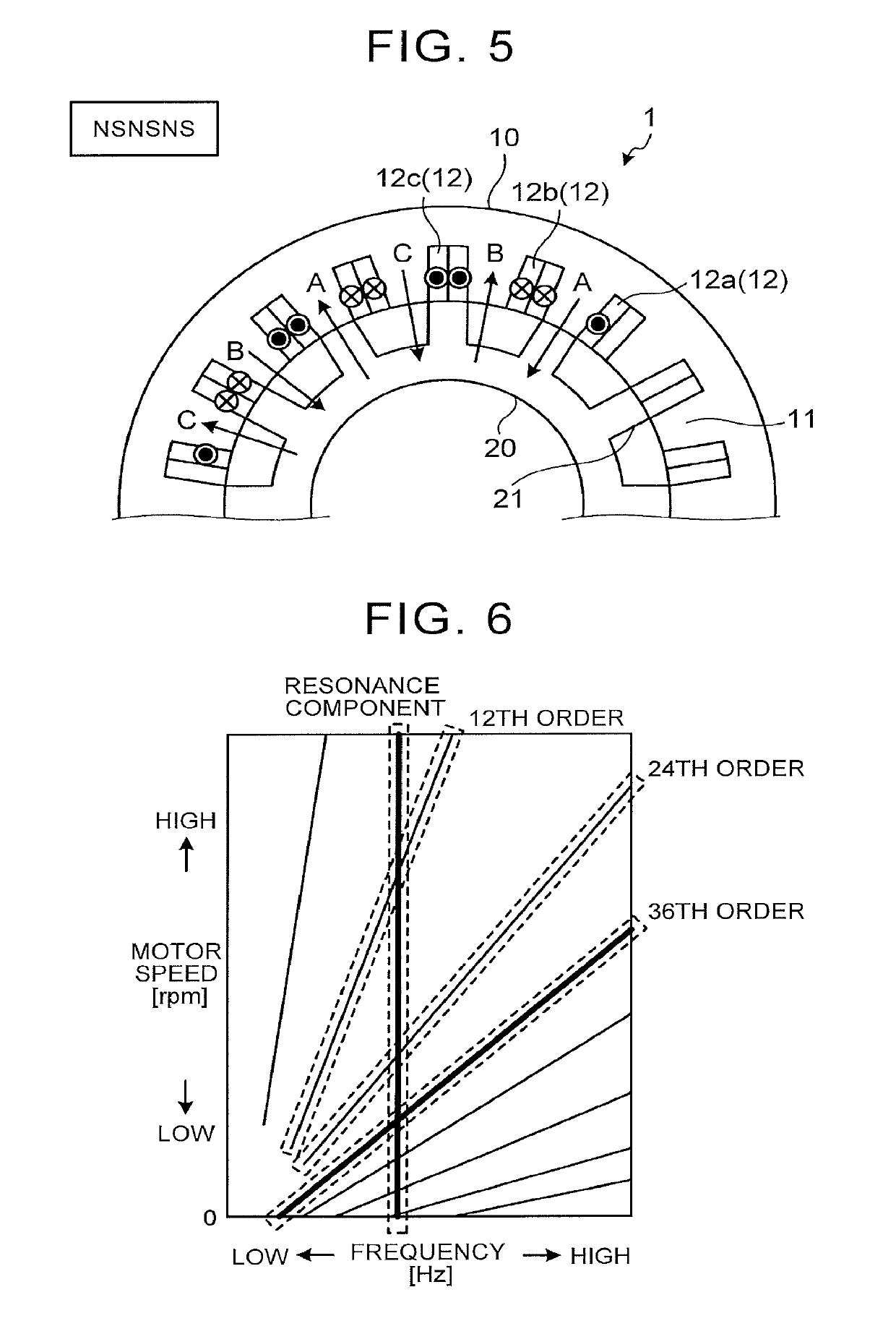
[0098]As described above, occurrence of resonance at a specific order is taken into consideration; therefore, when the SR motor 1 is driven in the NSNSNS pole configuration pattern, vibration and noise at the specific order can be reduced. More specifically, as the specific order, the least common multiple of the number of stator poles and the number of rotor poles, or an integral multiple of the product of the number of rotor poles and the number of coil phases is used. Then, when the pole configuration pattern is NSNSNS, excitation control is performed based on excitation conditions that are different for the respective phases, from the relationship between the excitation sound frequency at the specific order and the resonance frequency, so that the vibration and the noise can be reduced.

[0099]In the current waveform control as the noise reduction control, the excitation conditions are changed while the NSNSNS windings are maintained; thus, it is not necessary to switch the windi...

second embodiment

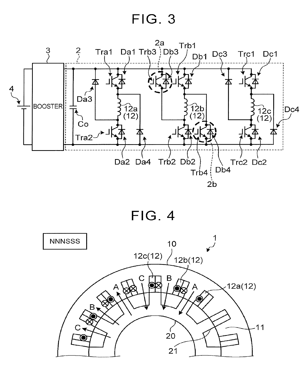
[0127]More specifically, in the inverter 2C of the second embodiment, a phase-A circuit includes two transistors Tra1, Tra2, and four diodes Da1, Da2, Da3, Da4, and a phase-B circuit includes two transistors Trb1, Trb2, and four diodes Db1, Db2, Db3, Db4, while a phase-C circuit incudes two transistors Trc1, Trc2, and four diodes Dc1, Dc2, Dc3, Dc4.

[0128]The current waveform control of the second embodiment can be performed according to the control flow shown in FIG. 11 as described above. In the second embodiment, step S2, step S8, and step S9 shown in FIG. 11 are eliminated. More specifically, after execution of step S1, the electronic control unit 100 proceeds to step S3. In the second embodiment, step S3 through step S7 subsequent to step S1 are executed in the same manner as those in the first embodiment. Thus, the control system of the second embodiment does not perform switching control of the pole configuration pattern, but performs excitation control (normal excitation cont...


PUM


Abstract

A switched reluctance motor system includes a switched reluctance motor, a rotor including a plurality of salient poles, a stator including a plurality of salient poles, coils of three phases wound around the salient poles of the stator, and an electronic control unit. The electronic control unit is configured to drive the switched reluctance motor in a pole configuration pattern of NSNSNS in which the salient poles of the stator that have different polarities are alternately arranged. The electronic control unit is configured to perform current waveform control when an excitation sound frequency of a given order coincides with a resonance frequency of the switched reluctance motor.

Description

INCORPORATION BY REFERENCE[0001]The disclosure of Japanese Patent Application No. 2017-084617 filed on Apr. 21, 2017 including the specification, drawings and abstract is incorporated herein by reference in its entirety.BACKGROUND1. Technical Field[0002]The disclosure relates to a switched reluctance motor system, and a method of controlling the switched reluctance motor system.2. Description of Related Art[0003]A switched reluctance motor including a stator and a rotor each having a plurality of salient poles, and coils wound around the salient poles of the stator, is known. In the switched reluctance motor, the salient poles of the stator are opposed to those of the rotor, and the rotor is rotated with magnetic attractive force generated between the salient poles of the stator and those of the rotor.[0004]In a technical article titled “Improvement of torque characteristic of a 50 kW SRM for HEV with a consideration of magnetic saturation of stator yoke”, The Japan Society of Appli...

Claims


Application Information

Patent Timeline
Patent Type & Authority Patents(United States)
IPC IPC(8): H02P25/08H02P25/086H02P25/098
CPCH02P25/098H02P25/086H02K19/10H02P25/08H02P25/0925
Inventor DEGUCHI, JUNICHISHIINA, TAKAHIROYOSHIZUE, KENSUKEHOSHI, NOBUKAZUKOBAYASHI, YUSUKEMURAKAMI, YOSUKEABE, TOMOYA
Owner TOYOTA JIDOSHA KK
Why Eureka
Try Eureka