Manipulation lever connection structure of vehicle

a technology of manipulation lever and connection structure, which is applied in the direction of steering device, mechanical control device, instruments, etc., can solve problems such as striking sound, and achieve the effect of removing striking sound

Inactive Publication Date: 2012-04-17
HONDA MOTOR CO LTD
View PDF13 Cites 8 Cited by
  • Summary
  • Abstract
  • Description
  • Claims
  • Application Information

AI Technical Summary

Benefits of technology

[0007]The invention has been made under such circumstances. It is an object of an embodiment of the invention to provide the manipulation lever connection structure of a vehicle which can eliminate a striking sound without losing an adjusting function using an adjustment nut.
[0009]According to an embodiment of the invention, it is possible to suppress the generation of a striking sound by the impact buffer member even when the adjustment nut vibrates due to vibrations of a vehicle body while enabling the adjustment of a position of the joint by the adjustment nut and avoiding a friction loss between the adjustment nut and the arm.
[0010]In such a construction, it is also preferable that a head portion of the adjustment nut has a hexagonal shape, a shaft portion of the adjustment nut is formed into a cylindrical shape having a diameter smaller than the diameter of the head portion of the adjustment nut, and the impact buffer member is mounted on the shaft portion. Due to such a construction, the head portion of the adjustment nut can have a hexagonal shape having the diameter larger than a diameter of the shaft portion. Thus, the fastening quantity of the adjustment nut can be easily adjusted and, at the same time, the removal of the impact buffer member mounted on the shaft portion can be prevented.
[0011]According to an embodiment of the invention, the manipulation lever connection structure of the vehicle includes the arm for operating the driving changeover device and for connecting the wire which extends from the manipulation lever to the arm. The adjustment bolt is mounted on the distal end of the wire, the joint is slidably mounted on the adjustment bolt on the axis of the adjustment bolt, and the adjustment nut which supports the joint is fastened to the adjustment bolt, the pair of joint support plate portions which respectively form the openings, having an elongated hole shape which allow the joint to pass therethrough, are mounted on the arm, and the adjustment nut is inserted between the pair of the joint support plate portions, and the impact buffer member is mounted on the adjustment nut with the clearance formed between the adjustment nut and the respective joint support plate portions. Accordingly, it is possible to eliminate a striking sound when the adjustment nut vibrates due to vibrations of the vehicle body without losing the adjusting function using the adjustment nut.
[0012]Further, the head portion of the adjustment nut has a hexagonal shape, the shaft portion of the adjustment nut is formed into a cylindrical shape having a diameter smaller than the diameter of the head portion, and the impact buffer member is mounted on the shaft portion. Thus, a fastening quantity of the adjustment nut can be easily adjusted and, at the same time, the removal of the impact buffer member can be prevented.

Problems solved by technology

Thus, when the adjustment nut vibrates due to vibrations of a vehicle body or the like, there exists a possibility that the adjustment nut and the arm come into contact with each other thus generating a striking sound.

Method used


Image

  • Manipulation lever connection structure of vehicle
  • Manipulation lever connection structure of vehicle
  • Manipulation lever connection structure of vehicle

Examples


Embodiment Construction

[0032]Hereinafter, one embodiment of the invention is explained in conjunction with the attached drawings. Here, in the explanation, the directions such as front and rear, left and right directions, and upper and lower directions are directions with respect to the directions of a vehicle body. Further, in the drawing, an arrow FR indicates a front side of the vehicle, and an arrow UP indicates an upper side of the vehicle body, respectively.

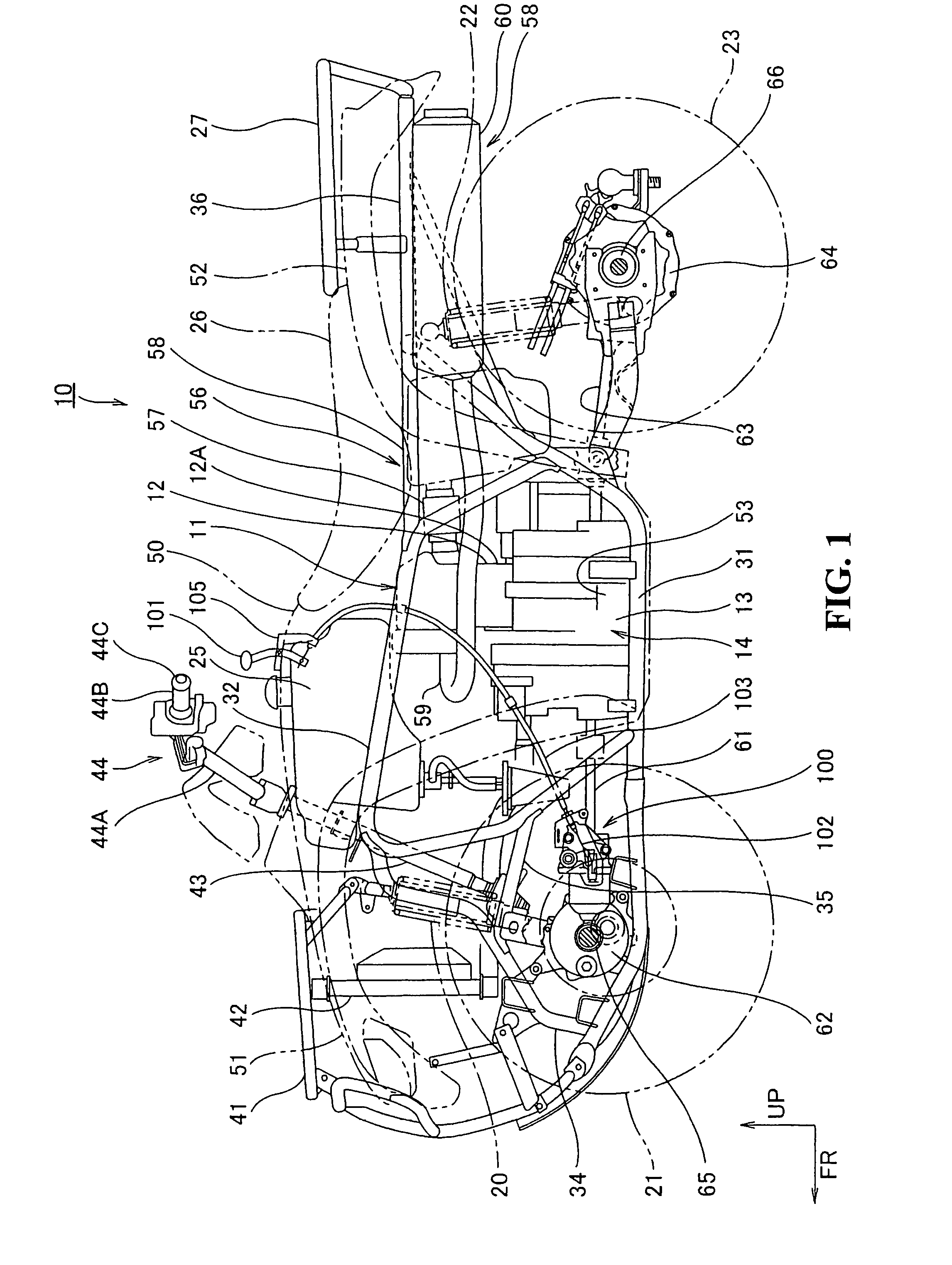
[0033]FIG. 1 is a side view of a vehicle 10 according to an embodiment of the invention. The vehicle 10 is a four-wheeled vehicle which is classified as an ATV suitable for traveling on a rough terrain (All Terrain Vehicle). Left and right front wheels 21, 21 (only front wheel 21 on a viewer's side shown is in FIG. 1) are respectively suspended from a front portion of a vehicle body frame 11 by way of a pair of left and right front shock absorbers 20, 20 (only shock absorber 20 on a viewer's side is shown in FIG. 1). Left and right rear wheels 23...


PUM


Abstract

A manipulation lever connection structure for a vehicle eliminates a striking sound without losing an adjusting function of an adjustment nut. The manipulation lever connection structure for a vehicle includes an arm for operating a driving changeover device and for connecting a wire which extends from a manipulation lever to the arm. An adjustment bolt is mounted on a distal end of the wire with a joint slidably mounted on the adjustment bolt on an axis thereof. An adjustment nut for supporting the joint is fastened to the adjustment bolt. A pair of side plate portions, respectively, forming elongated holes which allow the joint to pass therethrough is mounted on the arm. The adjustment nut is inserted between the pair of side plate portions with a buffer cover being mounted on the adjustment nut with a clearance formed between the adjustment nut and the respective side plate portions.

Description

CROSS-REFERENCE TO RELATED APPLICATIONS[0001]The present application claims priority under 35 USC 119 to Japanese Patent Application No. 2006-296538 filed on Oct. 31, 2006 the entire contents of which are hereby incorporated by reference.BACKGROUND OF THE INVENTION[0002]1. Field of the Invention[0003]The present invention relates to a manipulation lever connection structure of a vehicle for connecting a manipulation lever to a driving changeover device which can change over a driving state between two-wheel drive and four-wheel drive by way of a wire.[0004]2. Description of Background Art[0005]With respect to a conventional vehicle, a driving changeover device is known for changing over a driving state in response to a manipulation of a manipulation lever. With respect to this type of changeover device, a changeover device is known wherein the manipulation lever is connected to an arm of a driving changeover lever which operates the driving changeover device by way of a wire so as t...

Claims


Application Information

Patent Timeline
Patent Type & Authority Patents(United States)
IPC IPC(8): F16C1/10B60K20/00G05G1/04
CPCB60K23/08B62K5/01B62K21/26B62K23/02B62K23/06F16D13/752F16H61/36Y10T74/20612Y10T74/20287Y10T74/20098Y10T74/20408Y10T74/20085Y10T74/20438Y10T74/2028Y10T74/20402B60Y2200/124
Inventor YASUDA, KAZUHIROSATO, KOJIYANAI, HIDEO
Owner HONDA MOTOR CO LTD
Why Eureka
Try Eureka