
Driving mechanism and a bicycle using the same

a technology of driving mechanism and bicycle, which is applied in the direction of foot-driven levers, bicycles, transportation and packaging, etc., can solve the problems of bicycle storage disadvantages, the length of the whole bicycle is inevitable longer, and the distance between the front wheel and the rear wheel cannot be shortened, so as to shorten the length of the bicycle

Inactive Publication Date: 2012-04-17
WANG SUNG HUA
View PDF10 Cites 9 Cited by
  • Summary
  • Abstract
  • Description
  • Claims
  • Application Information

AI Technical Summary

Benefits of technology

"The present invention is a driving mechanism for bicycles that helps to make them shorter. It includes a transmission disc, a transmission belt, cranks, arms, connecting bodies, and pedals. The transmission disc is on the bicycle frame, the transmission belt surrounds it, and they are in relation. The cranks are on the sides of the bicycle, and they are connected to the transmission disc. The arms are on the sides of the bicycle, and they are connected to the cranks. The connecting bodies have two pivoting ends, and they are connected to the cranks and arms. The pedals are on the connecting bodies, and they move in an orbital motion. The distance between the topmost and bottommost points of the pedals' motion is reduced, which results in a shorter traveling distance for the user's feet and a shorter bicycle."

Problems solved by technology

However, the traveling orbit of the pedal is substantially a regular circle, thus the user's feet have to exercise in the circular traveling orbit.
As a result, the distance between the front wheel and the rear wheel cannot be shortened since it takes place for the user's feet to exercise.
Further, the length of the whole bicycle is inevitably longer, and thus the bicycle may have storage disadvantages.
Although the length thereof can be shortened, such collapsible bicycle cannot be ride once it is folded.

Method used


Image

  • Driving mechanism and a bicycle using the same
  • Driving mechanism and a bicycle using the same
  • Driving mechanism and a bicycle using the same

Examples


Embodiment Construction

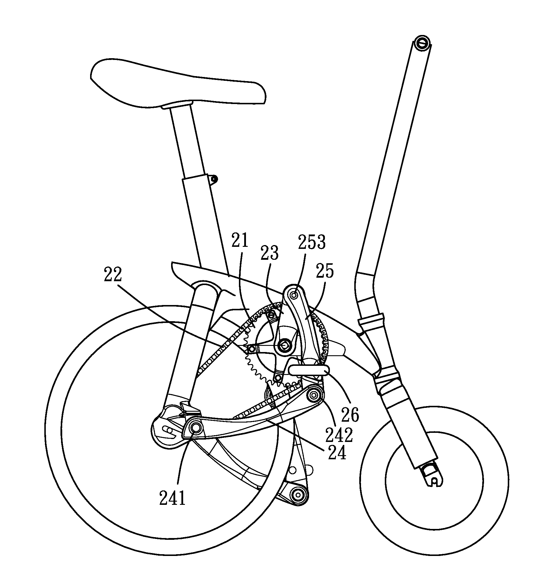
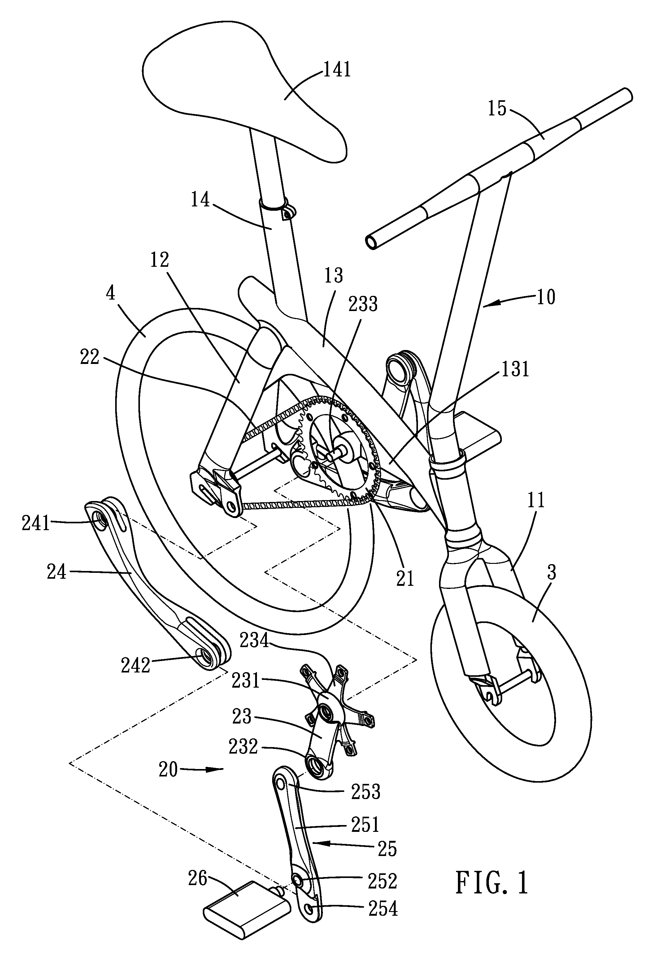
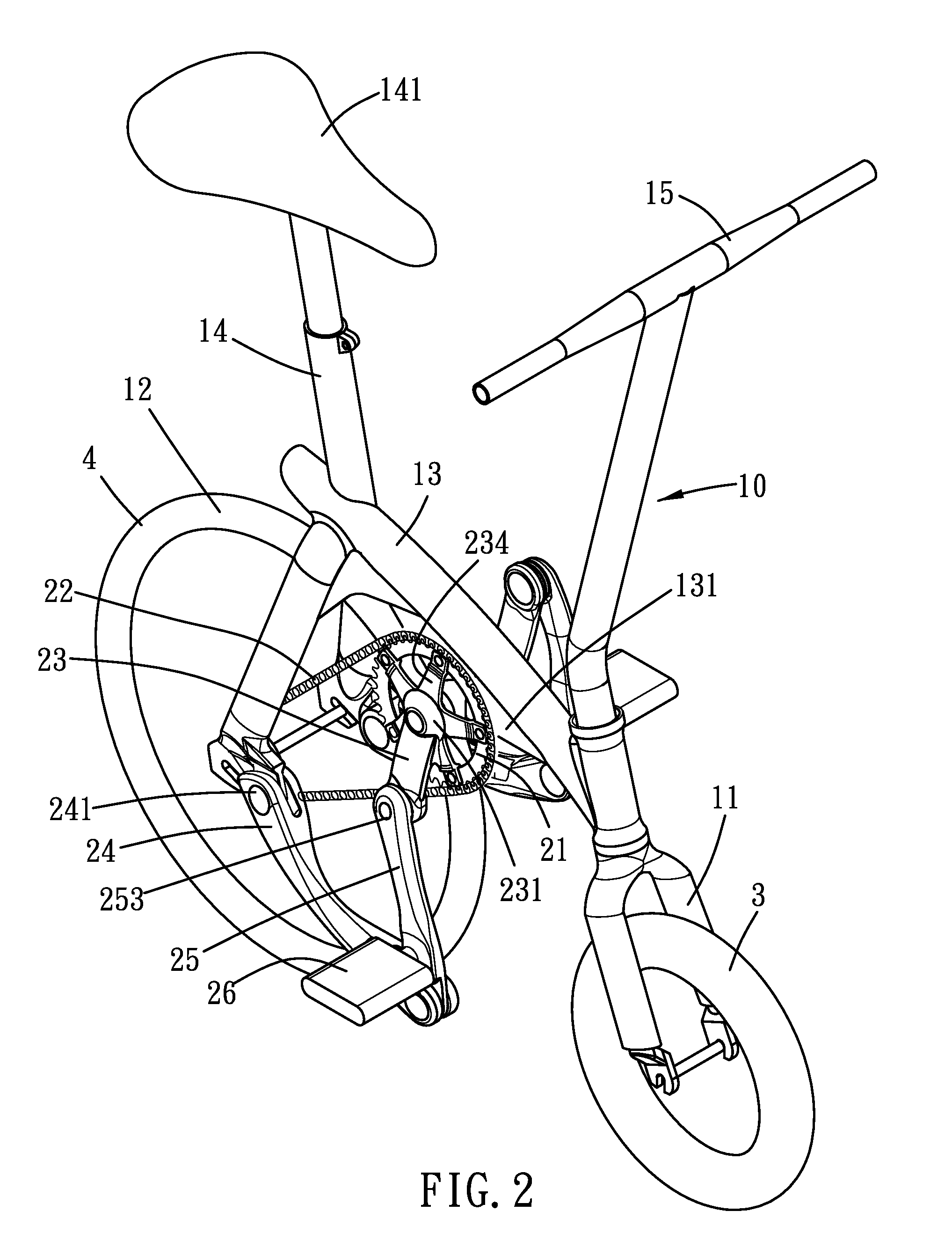
[0018]Please refer to FIG. 1 to FIG. 5. A bicycle of the present invention includes a frame 10, a front wheel 3, a rear wheel 4 and a driving mechanism 20. The frame 10 includes a front fork 11, a rear fork 12, a tube 13 connecting to the two forks, a seat tube 14 and a handle 15. The front wheel 3 and the rear wheel 4 are disposed on the front fork 11 and the rear fork 12 respectively. The diameter ratio of the front and rear wheels can be varied according to the driving mechanism and other factors.

[0019]A saddle 141 is disposed on the seat tube 14. The handle 15 is adapted to control the direction of the front wheel 3 or the rear wheel 4, depending on whether the bicycle is front-wheel-drive or rear-wheel-drive.

[0020]The driving mechanism 20 of the present invention includes a transmission disc 21, a transmission belt 22, a pair of cranks 23, a pair of arms 24, a pair of connecting bodies 25 and a pair of pedals 26. The transmission disc 21 is disposed on the frame 10, and the tra...


PUM


Abstract

A driving mechanism of the present invention includes a transmission disc, a transmission belt, a pair of cranks, a pair of arms, a pair of connecting bodies and a pair of pedals. The cranks and the arms are disposed on the frame of a bicycle, and the connecting bodies are disposed between distal ends of the cranks and the arms. Each pedal is disposed on the connecting body and is movable in an orbit. A vertical distance between the topmost point and the bottommost point of the orbit is H, and a horizontal distance between the front most point and a rearmost point is W, which satisfies the following relationship: H / W≧5 / 3.

Description

BACKGROUND OF THE INVENTION[0001]1. Field of the Invention[0002]The present invention relates to a driving mechanism for a bicycle and a bicycle using the same.[0003]2. Description of the Prior Art[0004]A conventional bicycle mainly includes a frame, a front wheel and a rear wheel. The front wheel and the rear wheel are disposed on a front fork and a rear fork of the frame respectively. A driving mechanism of the bicycle includes a chainwheel disposed on a seat tube of the frame, a pair of cranks disposed at the center of the chain wheel, a pair of pedals disposed on distal ends of the cranks, and a chain partially surrounding the chainwheel for driving the rear wheel. As such, the user can step on the pedals to rotate the chainwheel, and to further riding the bicycle forward.[0005]However, the traveling orbit of the pedal is substantially a regular circle, thus the user's feet have to exercise in the circular traveling orbit. As a result, the distance between the front wheel and th...

Claims


Application Information

Patent Timeline
Patent Type & Authority Patents(United States)
IPC IPC(8): B62M1/02B62M1/04B62M1/24B62M1/36
CPCB62K3/10B62M3/06B62M1/26
Inventor WANG, SHU-LING
Owner WANG SUNG HUA
Learn More