Wireless proximity probe and method of operating same

a proximity probe and wireless technology, applied in the direction of direction finders, direction finders using radio waves, instruments, etc., can solve the problems of unbalanced shafts, increased mass of devices in which coils are installed, and state-of-the-art proximity probes

Active Publication Date: 2012-04-17
BAKER HUGHES INC
View PDF8 Cites 11 Cited by
  • Summary
  • Abstract
  • Description
  • Claims
  • Application Information

AI Technical Summary

Problems solved by technology

Such vibrations can be indicative of wear of the bearing or the shaft, or of an unbalanced shaft.
Generally, known magnetic wire wound coils are larger than the antennas used to transmit and / or receive microwave signals, and as such, such coils may be expensive to manufacture and may increase the mass of the device in which the coils are installed.
Lastly, known state-of-the-art proximity probes that need physical wires to provide electrical power and / or carry data transmission can require complex wiring schemes.
Over time, such wiring and associated electrical connections may fail.
Moreover, the physical constraints of wiring can limit the areas that the proximity probes may be positioned relative to a target object.

Method used


Image

  • Wireless proximity probe and method of operating same
  • Wireless proximity probe and method of operating same
  • Wireless proximity probe and method of operating same

Examples


Embodiment Construction

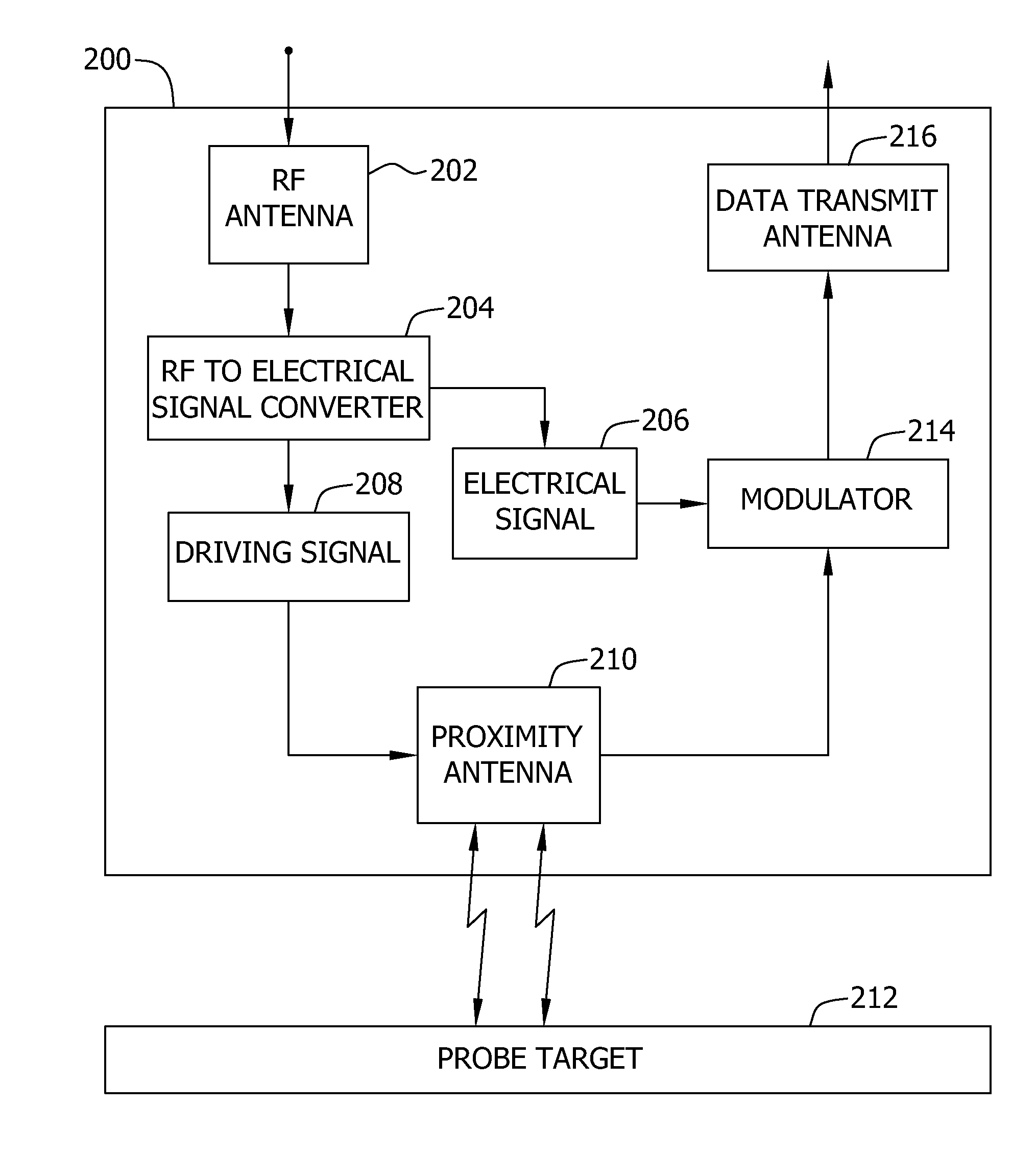
[0014]The present application describes a wireless proximity probe that is suitable for placement in environments where the use of wires may be problematic or inconvenient. Use of wireless proximity probes eliminates the need to extend cables to the proximity probes that are used to monitor an object. Installing cables may be time consuming, expensive, and / or difficult. As such, the present application describes a proximity probe that does not require wires for each probe, but merely uses a transmitting device coupled to a power supply, and a receiving device coupled to receive proximity measurements, from one or more wireless proximity probes.

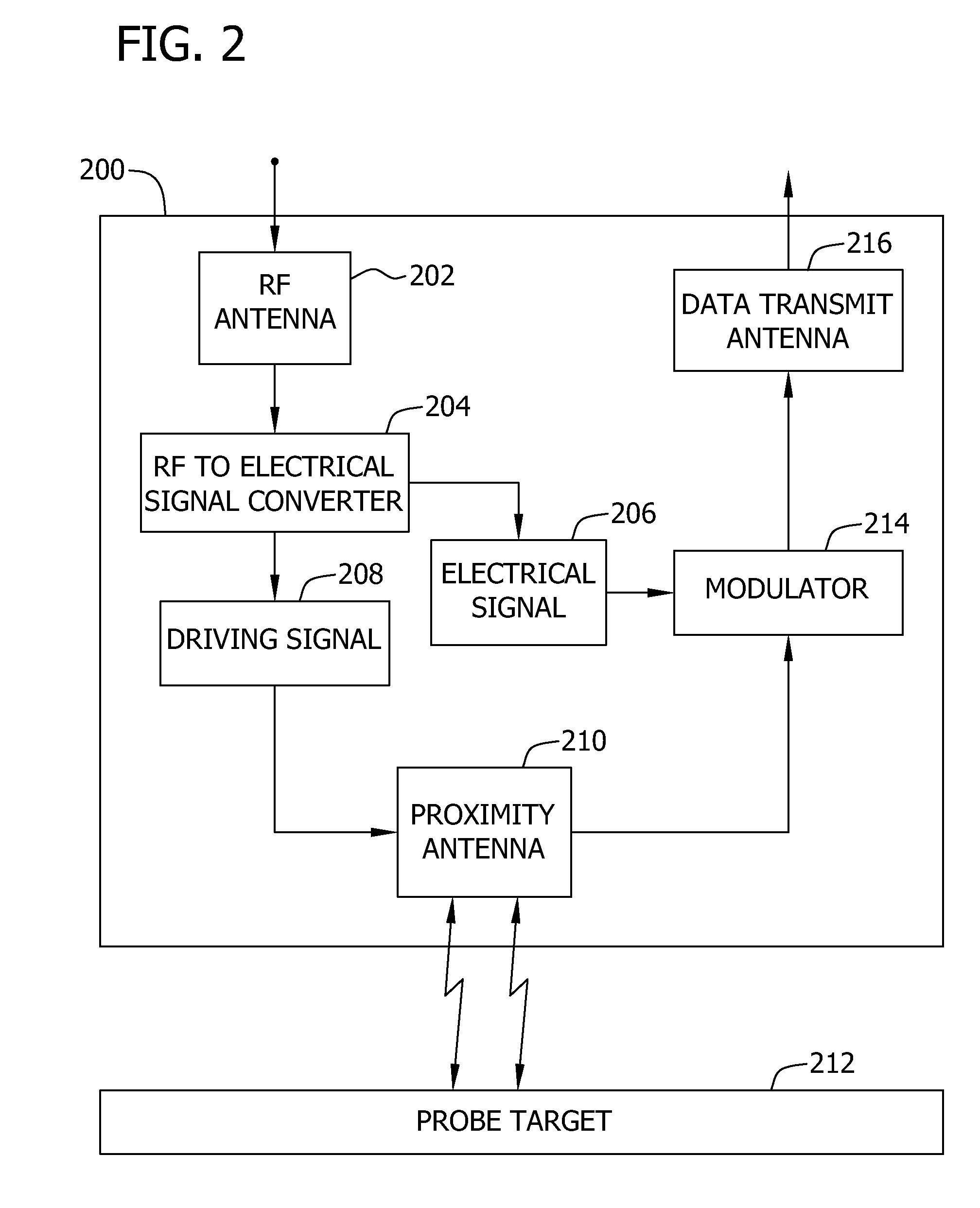
[0015]FIG. 2 is a block diagram illustrating an exemplary wireless proximity probe 200. In the exemplary embodiment, probe 200 continuously measures and / or monitors rotating machinery components, such as, rotating machinery components in a turbine. In another embodiment, probe 200 operates non-continuously and only measures and / or monitors whe...


PUM


Abstract

A proximity probe, for use in determining a distance to a probe target, includes a first antenna configured to wirelessly receive a radio-frequency signal at a first predetermined frequency and a converter configured to convert the received signal to a driving signal and to an electrical signal. The proximity probe also includes a second antenna configured to receive power via the driving signal and to generate a signal indicative of a distance from the proximity probe to the probe target, and a third antenna configured to transmit the generated signal.

Description

BACKGROUND OF THE INVENTION[0001]The invention relates generally to proximity probes, and more particular, to an apparatus and method for operating a proximity probe for detecting a proximity to a probe target in which the proximity probe is wirelessly coupled to a power source.[0002]During use, known proximity probes are used to detect a distance between the proximity probe and a target object, such as a turbine shaft. The data obtained by the probe can be used to accurately measure the vibration that the shaft is experiencing. Such vibrations can be indicative of wear of the bearing or the shaft, or of an unbalanced shaft.[0003]Some known proximity probes are eddy current (EC) devices that measure the interaction between an electromagnetic field generated by the EC device and the target object being measured. At least some of such known EC devices include a sensing coil that generates a magnetic field. When the sensing coil is positioned adjacent to a conductive component, an eddy...

Claims


Application Information

Patent Timeline
Patent Type & Authority Patents(United States)
IPC IPC(8): G01S3/02
CPCG01S13/08G01S13/75
Inventor FOLDEN, DWAYNE ANDREWSHEIKMAN, BORIS LEONID
Owner BAKER HUGHES INC
Why Eureka
Try Eureka