Observation device and wavelength limiting filter

a wavelength limiting filter and observation device technology, applied in the field of observation device and wavelength limiting filter, can solve the problem of inability to distinguish whether various changes occurred on images, and achieve the effect of suppressing changes in images

Active Publication Date: 2012-04-17
NIKON CORP
View PDF20 Cites 16 Cited by
  • Summary
  • Abstract
  • Description
  • Claims
  • Application Information

AI Technical Summary

Benefits of technology

[0014]According to an observation device and a wavelength limiting filter for the observation device of the present invention, it is possible to suppress a change of an image resulting from an additive, and to enable to generate an appropriate image in an automatic observation.

Problems solved by technology

However, there is a problem that it is impossible to distinguish whether various changes occurred on an image is resulting from the change of the sample or resulting from the additive, because the brightness and the contrast of a generated image may change when an automatic observation is performed by using an imaging apparatus such as a camera.

Method used


Image

  • Observation device and wavelength limiting filter
  • Observation device and wavelength limiting filter
  • Observation device and wavelength limiting filter

Examples


modification example

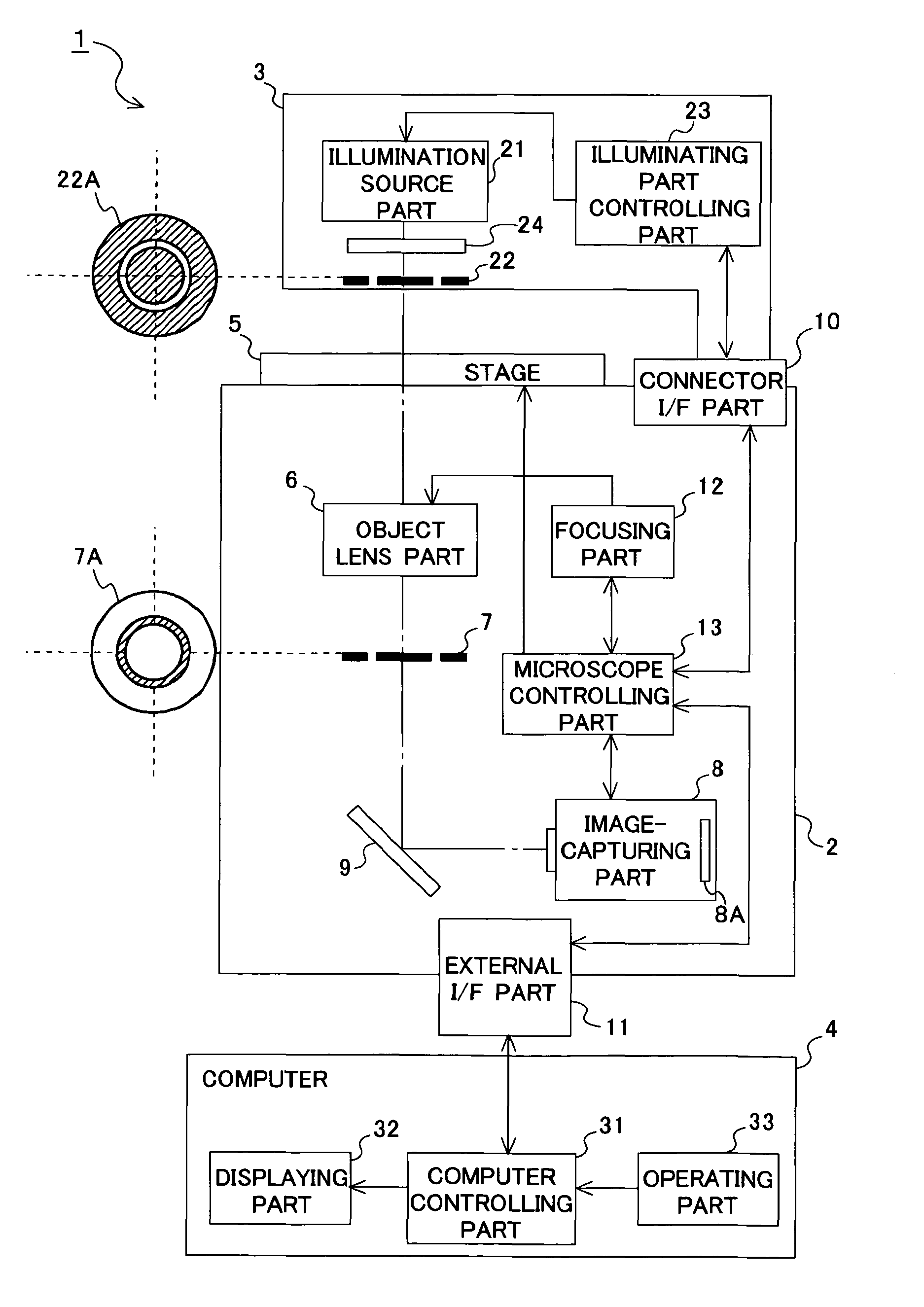
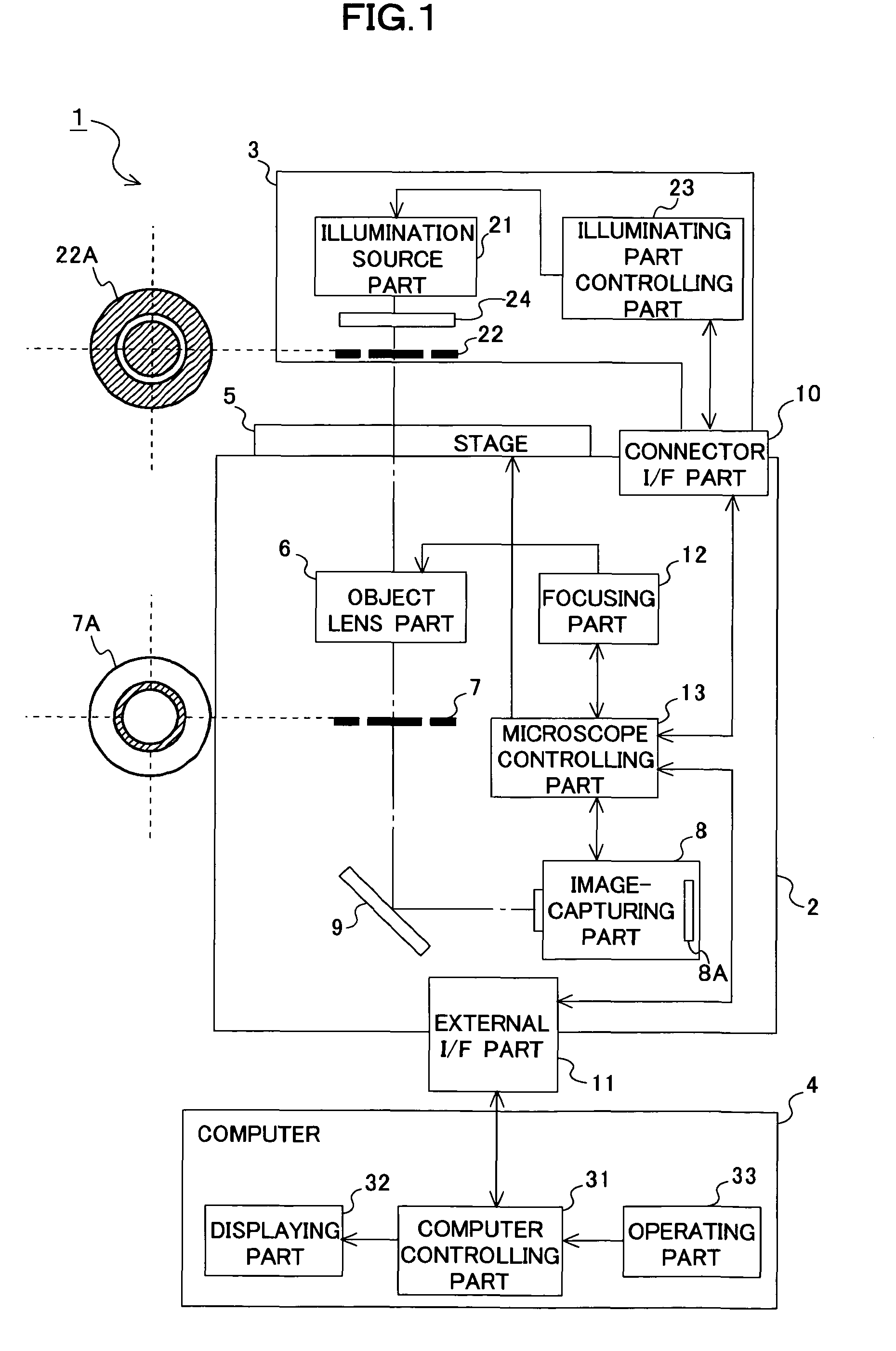
[0059]In the present embodiment, an example is illustrated in which the wavelength limiting filter 24 is placed between the illumination source part 21 and the ring aperture 22, but it may be placed at any position as long as it is between the illumination source part 21 and the image-capturing part 8 and on the optical axis of the illumination source part 21. A disposed position of the wavelength limiting filter 24 may be determined in accordance with the wavelengths limited by the wavelength limiting filter 24 and the constitution of the microscope 1. A flowchart until the light irradiated from the illumination source part 21 reaches the imaging sensor 8A and the image is generated when the wavelength limiting filter 24 is placed between the stage 5 and the image-capturing part 8 is illustrated in FIG. 12. As illustrated in FIG. 12, the incident light Iin(λ) is similar to the case in FIG. 6 even though the position placing the wavelength limiting filter 24 is changed.

[0060]Besides...


PUM


Abstract

An observation device observing a sample cultured in a culture vessel includes an illuminating unit including an illumination optical system and illuminating the sample, an image-capturing unit including an imaging sensor and generating an image by capturing an image of the sample illuminated by the illuminating unit, and a wavelength limiting filter being placed on an optical axis of the illumination optical system and between the illuminating unit and the image-capturing unit, and limiting a part of wavelengths of an illumination light from the illumination optical system in accordance with optical absorption properties of an additive contained in a culture medium used for culturing the sample. Accordingly, it is possible to suppress a change of the image resulting from the additive and to enable to generate an appropriate image in an automatic observation.

Description

CROSS REFERENCE TO THE RELATED APPLICATIONS[0001]This application is a continuation application of International Application PCT / JP2008 / 000593, filed Mar. 14, 2008, designating the U.S., and claims the benefit of priority from Japanese Patent Application No. 2007-071099, filed on Mar. 19, 2007, the entire contents of which are incorporated herein by reference.BACKGROUND[0002]1. Field[0003]The present application relates to an observation device observing a sample cultured in a culture vessel, and a wavelength limiting filter for the observation device.[0004]2. Description of the Related Art[0005]Conventionally, a phase-contrast microscope or the like is known as an observation device observing a sample cultured in a culture vessel (for example, refer to Patent Document 1: Japanese Unexamined Patent Application Publication No. H11 -84260). There are various microorganisms, cells, and so on as the samples observed by the observation device as stated above.[0006]Incidentally, it is oft...

Claims


Application Information

Patent Timeline
Patent Type & Authority Patents(United States)
IPC IPC(8): G01J3/51G02B21/00
CPCG01N21/25G02B21/14Y10S435/808
Inventor KIYOTA, YASUJIRO
Owner NIKON CORP
Why Eureka
Try Eureka