Current measuring device and processing unit comprising one such device

a technology of current measuring device and processing unit, which is applied in the direction of constant-current supply dc circuit, emergency protective arrangement for limiting excess voltage/current, instruments, etc., can solve the problems of amplification of noise and stray signals, dependable circuits introduce large measurement errors, and amplification of offsets of amplifiers or other electronic circuits. , to achieve the effect of simple and reliable structure, wide dynamic measuring range, and weak input impedan

Active Publication Date: 2012-04-17
SCHNEIDER ELECTRIC IND SAS
View PDF9 Cites 29 Cited by
  • Summary
  • Abstract
  • Description
  • Claims
  • Application Information

AI Technical Summary

Benefits of technology

[0007]The object of the invention is to provide a current measuring device having a wide dynamic measuring range, a weak input impedance, and a simple and dependable structure. It is a further object of the invention to provide a processing unit comprising one such measuring device.

Problems solved by technology

However weak resistance values require the use of high-gain signal amplifiers.
Large gains also cause amplification of the noise and of the stray signals that are particularly present in industrial environments.
Increasing the gain also leads to excessive amplification of the offset of the amplifier or of the other electronic circuits.
However, these complex and not very dependable circuits also introduce large measurement errors.

Method used


Image

  • Current measuring device and processing unit comprising one such device
  • Current measuring device and processing unit comprising one such device
  • Current measuring device and processing unit comprising one such device

Examples


Embodiment Construction

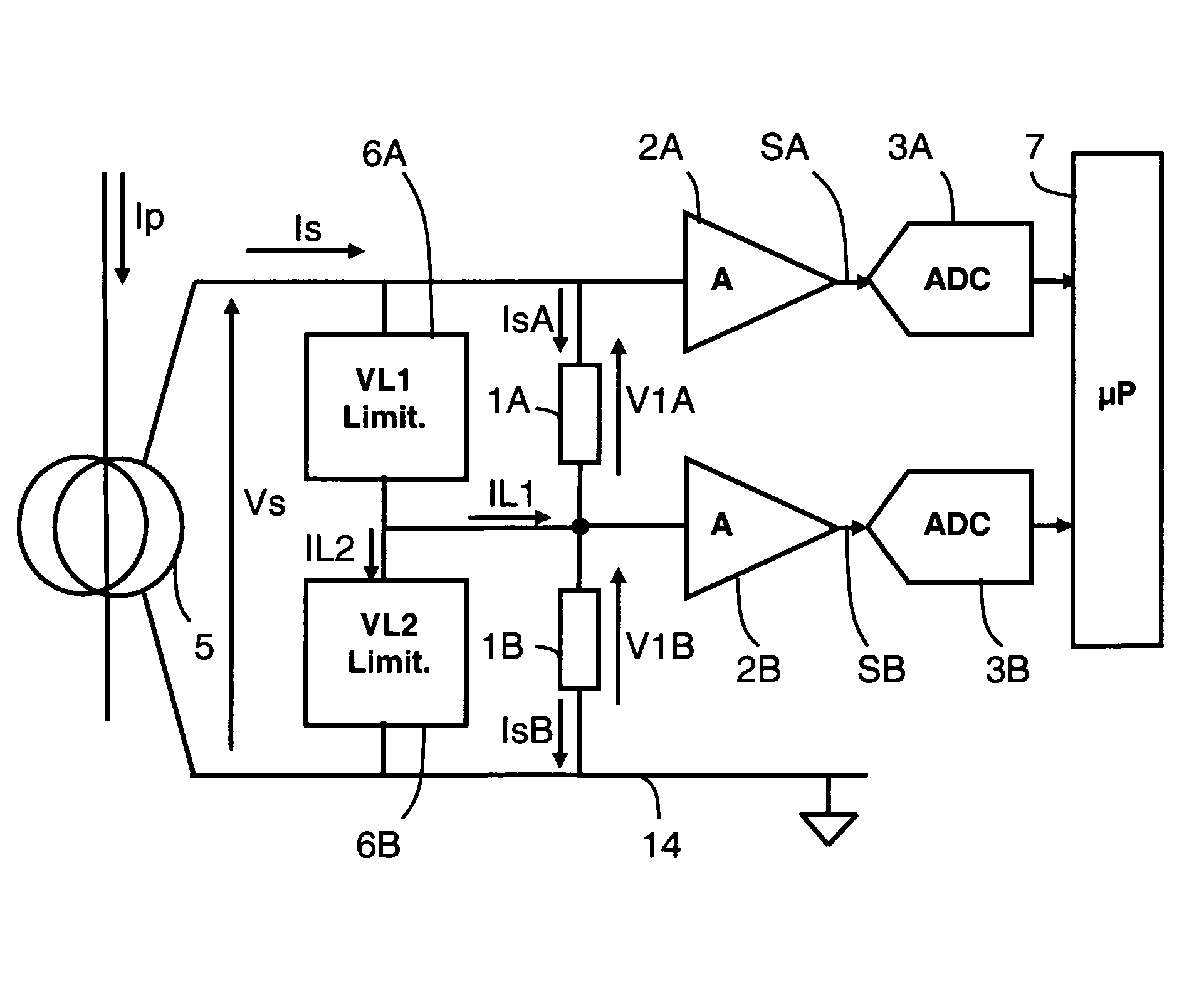
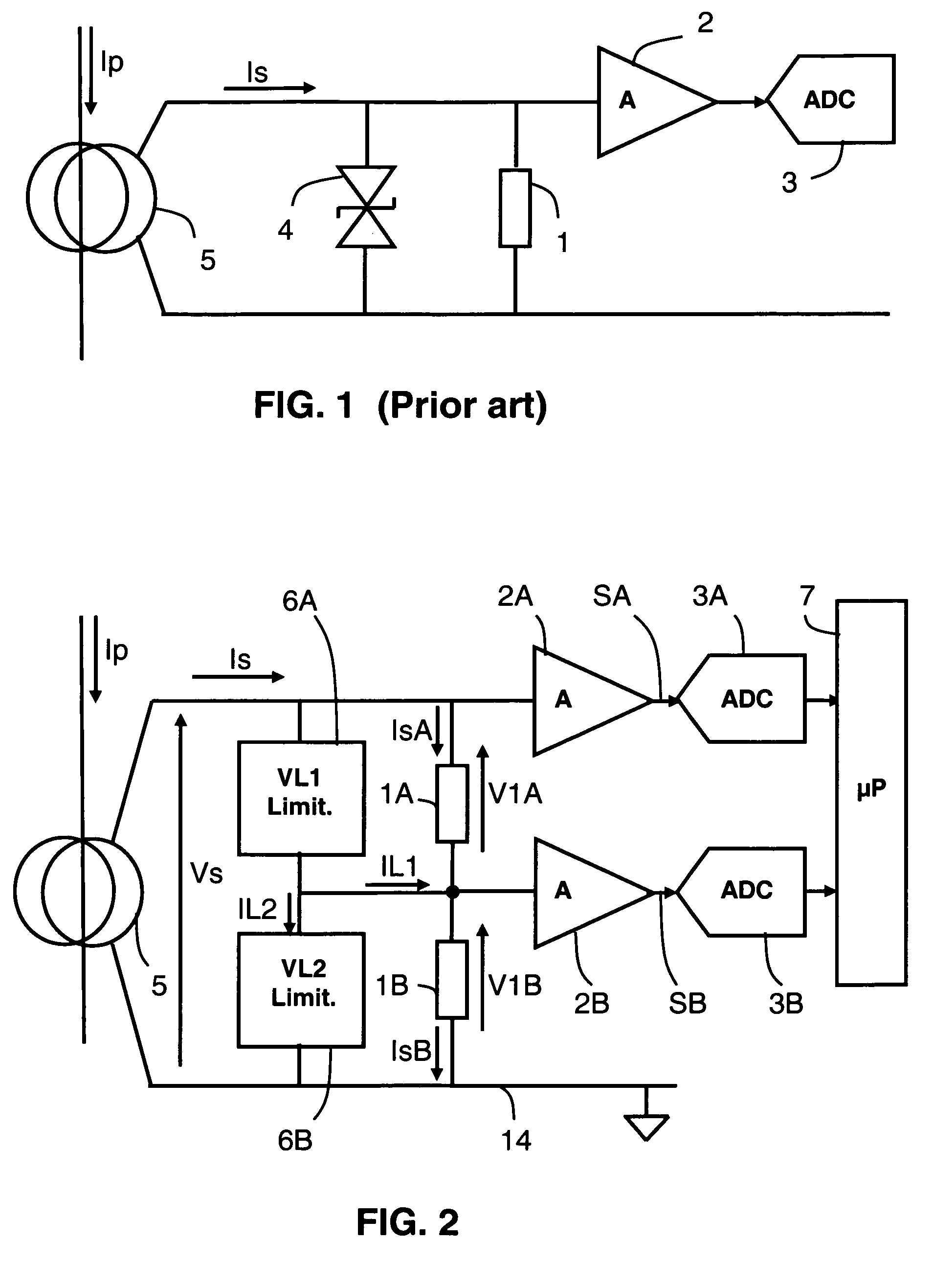
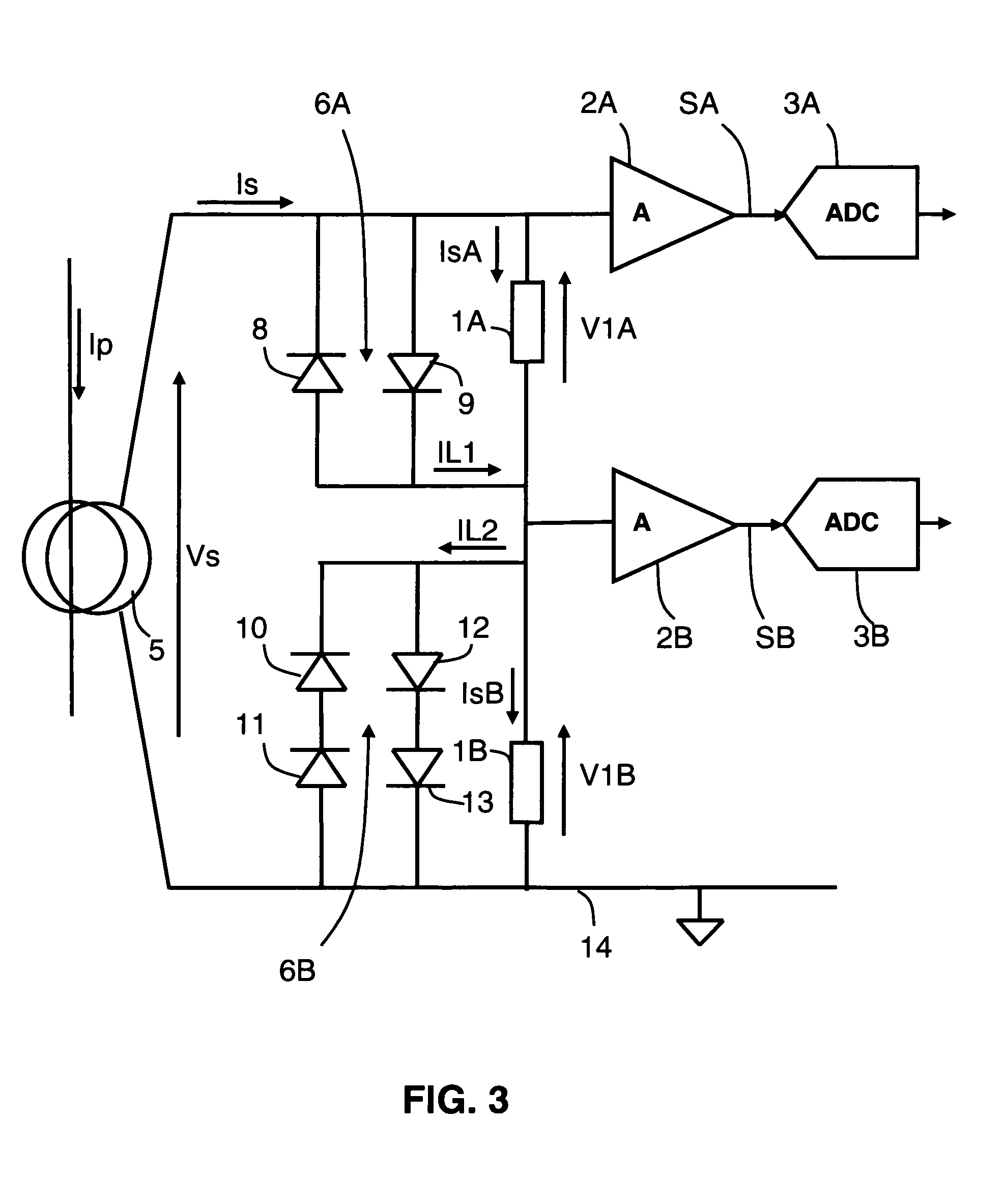
[0031]A current measuring device according to an embodiment of the invention described in FIG. 2 comprises a first measuring resistor 1A to receive a measurement current IsA, and a first signal amplifier 2A having an input connected to said first measuring resistor 1A and an output to provide a first measurement signal SA. According to this embodiment of the invention, the device advantageously comprises a second measuring resistor 1B connected in series with said first resistor 1A, the value of first measuring resistor 1A being greater than the value of second measuring resistor 1B. The first measuring resistor 1A is designed for measuring weak currents whereas resistor 1B of very low value is designed for measuring strong currents. A first voltage limiter 6A is connected in parallel on first measuring resistor 1A of higher value to branch off a shunt current IL1 to second measuring resistor 1B as soon as a first voltage threshold VL1 is exceeded.

[0032]In the device represented in ...


PUM


Abstract

The current measuring device comprises a first measuring resistor to receive a measurement current, and a first signal amplifier having an input connected to said first measuring resistor and an output to provide a first measurement signal. A second measuring resistor is connected in series with said first measuring resistor, and first voltage limiting means are connected in parallel on the first measuring resistor to branch a first shunt current off when a first limiting voltage is reached on said first measuring resistor. The value of the first measuring resistor is greater than the value of the second measuring resistor A processing unit comprises one such current measuring device.

Description

BACKGROUND OF THE INVENTION[0001]The invention relates to a current measuring device comprising:[0002]a measuring resistor to receive a measurement current from a current sensor, and[0003]a signal amplifier having an input connected to said measuring resistor and an output to provide a measurement signal representative of a current to be measured.STATE OF THE ART[0004]Known current measuring devices such as the one represented in FIG. 1 generally comprise a measuring resistor 1 of low value to receive a current to be measured. In order to greatly reduce the value of the measuring resistor, devices with a wide dynamic measuring range also comprise a signal amplifier 2 connected to the measuring resistor to amplify the signal of weak value due to the very low value of the measuring resistor. An analog-to-digital signal converter connected to an output of the amplifier provides a digital signal representative of the current flowing through the measuring resistor. Generally, the measuri...

Claims


Application Information

Patent Timeline
Patent Type & Authority Patents(United States)
IPC IPC(8): G01R15/00H02H9/00G01R19/00G01R31/08H02J1/04H02H3/08
CPCG01R15/09G01R19/0092G01R15/18Y10T307/438
Inventor KALENINE, YVAN
Owner SCHNEIDER ELECTRIC IND SAS
Why Eureka
Try Eureka