
Current measurement device and processing unit comprising such a device

一种测量设备、电流测量的技术,应用在测量装置、只测电流、测量电变量等方向,能够解决不很可靠电路、大测量误差等问题

Active Publication Date: 2009-12-16
SCHNEIDER ELECTRIC IND SAS
View PDF5 Cites 7 Cited by
  • Summary
  • Abstract
  • Description
  • Claims
  • Application Information

AI Technical Summary

Problems solved by technology

However, these complex and not very reliable circuits also introduce large measurement errors

Method used


Image

  • Current measurement device and processing unit comprising such a device
  • Current measurement device and processing unit comprising such a device
  • Current measurement device and processing unit comprising such a device

Examples


Embodiment Construction

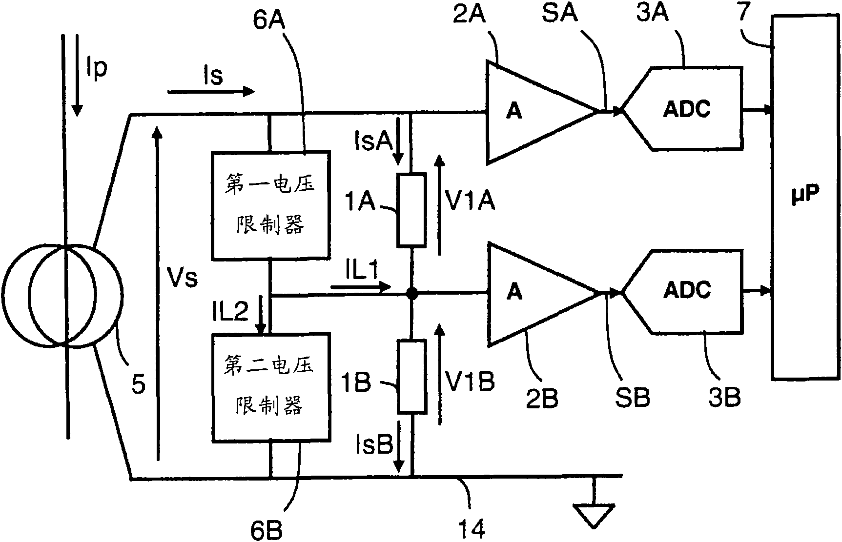
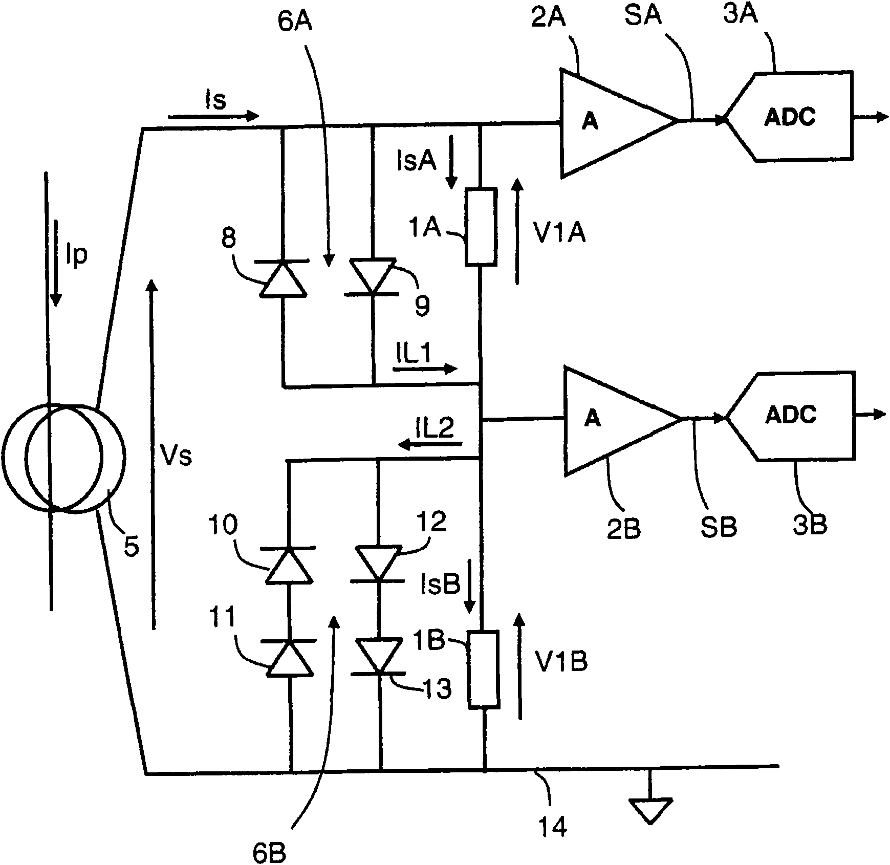
[0032] figure 2 The described current measuring device according to an embodiment of the invention comprises a first measuring resistor 1A receiving a measuring current IsA, and having an input connected to said first measuring resistor 1A and an output providing a first measuring signal SA end of the first signal amplifier 2A. According to this embodiment of the invention, the device advantageously comprises a second measuring resistor 1B connected in series with said first resistor 1A, the value of the first measuring resistor 1A being greater than the value of the second measuring resistor 1B. The first measuring resistor 1A is designed to measure weak currents, while the very low value resistor 1B is designed to measure strong currents. A first voltage limiter 6A is connected in parallel with the higher value first measuring resistor 1A for shunting the shunt current IL1 to the second measuring resistor 1B once the first voltage threshold VL1 is exceeded.

[0033] exist...


PUM


Abstract

The current measuring device comprises a first measuring resistor to receive a measurement current, and a first signal amplifier having an input connected to said first measuring resistor and an output to provide a first measurement signal. A second measuring resistor is connected in series with said first measuring resistor, and first voltage limiting means are connected in parallel on the first measuring resistor to branch a first shunt current off when a first limiting voltage is reached on said first measuring resistor. The value of the first measuring resistor is greater than the value of the second measuring resistor A processing unit comprises one such current measuring device.

Description

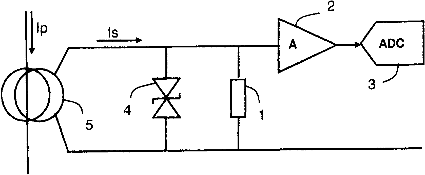
technical field [0001] The invention relates to current measuring equipment comprising: [0002] - the measuring resistor, which receives the measuring current from the current sensor, and [0003] - A signal amplifier having an input connected to said measuring resistor and an output providing a measurement signal representative of the current to be measured. Background technique [0004] such as figure 1 The known current measuring device shown generally comprises a low value measuring resistor 1 for receiving the current to be measured. In order to greatly reduce the value of the measuring resistor, the device with a wide dynamic measuring range also includes a signal amplifier 2 connected to the measuring resistor to amplify signals of weak values ​​due to very low values ​​of the measuring resistor. An analog-to-digital signal converter connected to the output of the amplifier provides a digital signal representative of the current flowing through the measurement res...

Claims


Application Information

Patent Timeline
Patent Type & Authority Applications(China)
IPC IPC(8): G01R19/00G01R15/09
CPCG01R15/18G01R19/0092G01R15/09
Inventor 伊范·卡莱尼内
Owner SCHNEIDER ELECTRIC IND SAS
Learn More