System and method to expand tubulars below restrictions

a technology of expansion and tubulars, applied in the field of expansion of tubulars, can solve the problems of increasing the minimum wall thickness requirements of the expandable tubulars to resist collapse or burst forces exerted by these pressures, and the expansion force is limited to about 10%, so as to reduce the expansion force necessary

Inactive Publication Date: 2012-04-24
WEATHERFORD TECH HLDG LLC
View PDF22 Cites 6 Cited by
  • Summary
  • Abstract
  • Description
  • Claims
  • Application Information

AI Technical Summary

Benefits of technology

[0017]In one embodiment, a method for expanding a tubular below a restriction in a wellbore comprises running the tubular past the restriction, wherein the tubular comprises a first end, a second end, and one or more grooves that extend substantially along the length of the tubular from the first end to the second end and expanding the tubular, wherein the one or more grooves are configured to reduce an expansion force necessary to expand the tubular.

Problems solved by technology

During the formation or after the completion of a wellbore, occasionally, a leak may develop at some point along a length of a tubular that permits the loss of well fluids into the surrounding environment behind the tubular or permits the introduction of unwanted fluids into the tubular and the wellbore.
There are several problems, however, associated with the expansion of tubulars in general.
First, expandable tubulars are limited to an expansion of about 10%-25% of their original diameter using existing expansion practices.
Second, as the expandable tubulars are subjected to higher pressures in the wellbore, the minimum wall thickness requirements for the expandable tubulars to resist collapse or burst forces exerted by these pressures significantly increase.
Finally, the running tools and the expansion tools themselves continue to face strict dimensional limitations as the inner diameter of the wellbore typically decreases with increasing depth of the wellbore.
These problems are exacerbated when the expansion of tubulars may be utilized to address a defect below a restriction in the wellbore.
As mentioned above, these restrictions pose additional severe constraints in running standard expandable tools into the wellbore.
These restrictions also demand the use of high expansion ratio expandable liners, which require high expansion forces.
Further, smaller diameter wellbores require smaller diameter expandable tubulars, which geometrically leads to larger expansion ratios.
When using hydraulic pressure to expand a tubular, due to the high pressure required, weaknesses in the tubular are exploited limiting the amount of expansion that can be achieved before the tubular ruptures.
The disadvantages of these devices include unreliable sealing and a considerable reduction in the flow area, which affects production of the well.
Longitudinally corrugated pipes have also been proposed but connecting such pipes still remains a challenge.

Method used


Image

  • System and method to expand tubulars below restrictions
  • System and method to expand tubulars below restrictions
  • System and method to expand tubulars below restrictions

Examples


Embodiment Construction

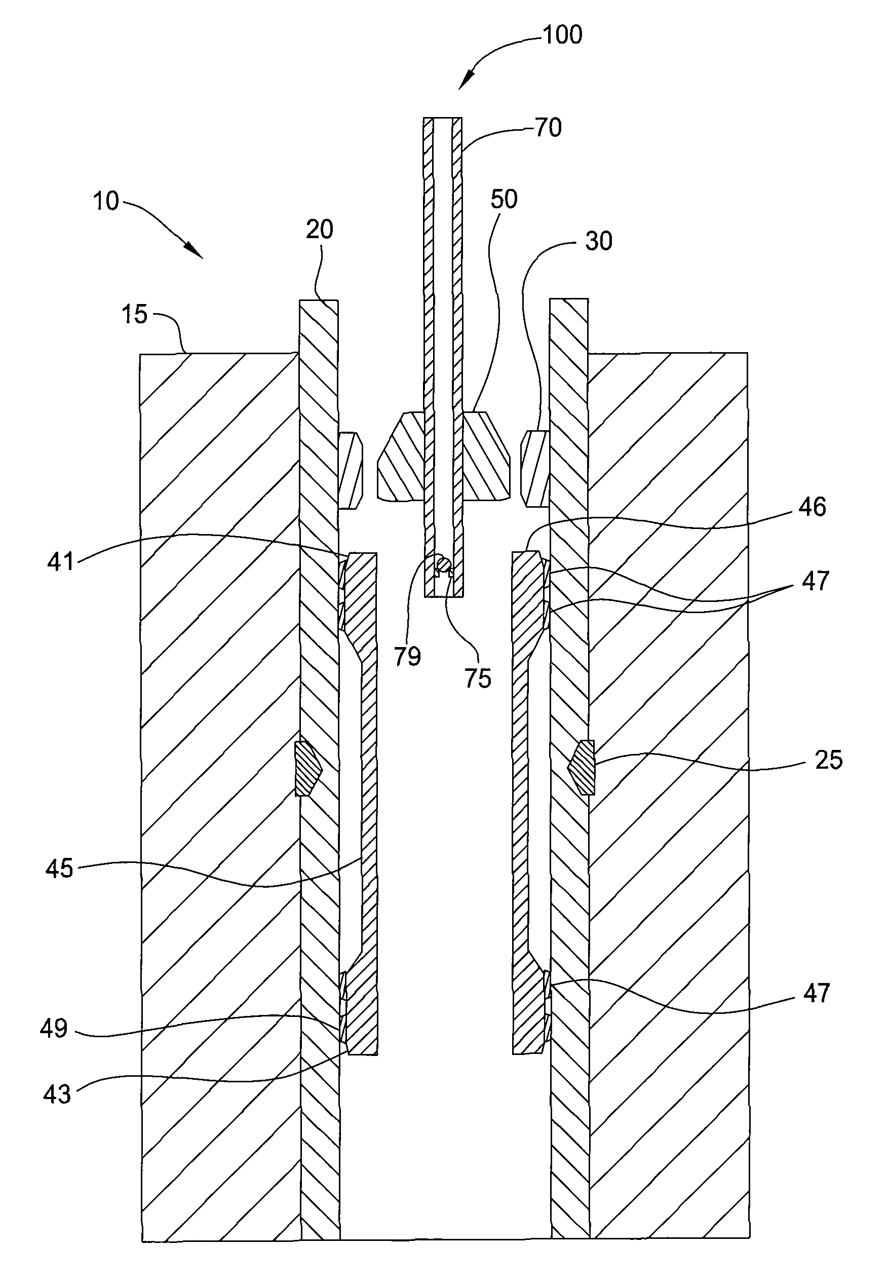
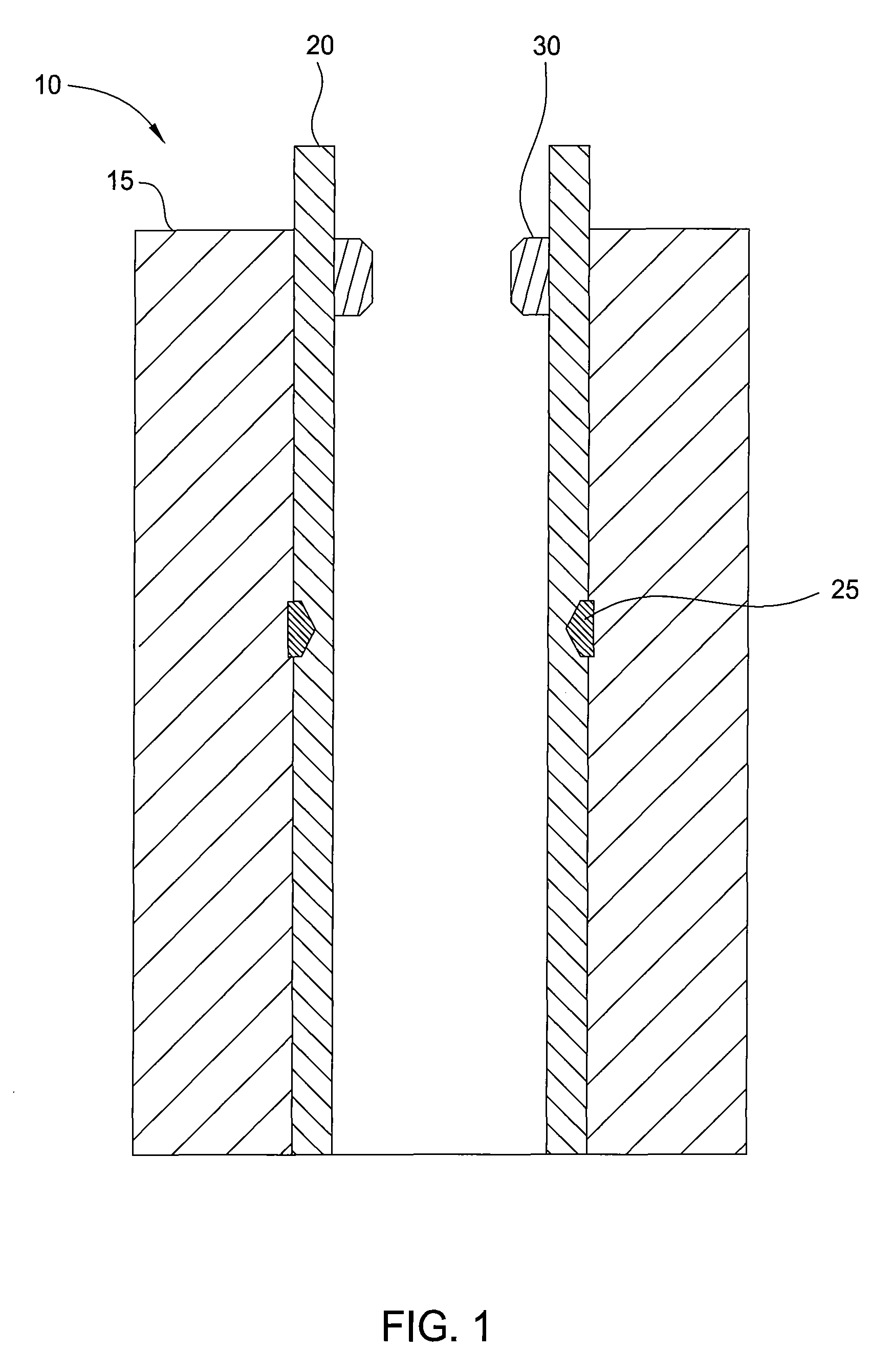
[0038]FIG. 1 illustrates a wellbore 10 having a casing 20 disposed in an earthen formation 15. The casing 20 may be cemented in the formation 15 and may include multiple sections of casings coupled together to form the casing 20. Located along the length of the casing 20 is a defect 25, such as a leaking connection or a fracture in the wall of the casing 20. The defect 25 may permit the loss of a fluid, such as a liquid or a gas, into the surrounding earthen formation 15 or permit the introduction of unwanted fluids into the casing 20 of the wellbore 10. As a result, dangerous pressure fluctuations may occur during the formation or completion of the wellbore 10. The defect 25 is located below a restriction 30 in the wellbore 10. The restriction 30 may be a downhole packer, safety valve, landing profile, lubricator, tubular, or other obstruction which reduces the inner diameter of the wellbore 20 above the defect 25. The restriction 30 may include a much smaller inner diameter than t...


PUM


Abstract

A method and apparatus for expanding a tubular below a restriction in a wellbore. An expandable tubular may comprise a first end having a first wall thickness, a second end having a second wall thickness, and a middle section disposed between the first and second ends and having a third wall thickness that is less than the first and second wall thicknesses. The first and second ends may include one or more grooves disposed along a length of the ends. A method for expanding a tubular below a restriction in a wellbore may comprise running the tubular past the restriction, wherein the tubular comprises a first end and a second end, each end having a wall thickness greater than a wall thickness of a middle section disposed between the ends. The method may include expanding the tubular, wherein the first and second ends of the expanded tubular have outer diameters greater than the outer diameter of the middle section.

Description

BACKGROUND OF THE INVENTION[0001]1. Field of the Invention[0002]Embodiments of the invention generally relate to expanding tubulars in a wellbore. More particularly, embodiments of the invention relate to the expansion of tubulars below restrictions located in the wellbore. More particularly still, embodiments of the invention relate to an expandable tubular configured to be expanded below restrictions located in the wellbore.[0003]2. Description of the Related Art[0004]Oil & gas and other types of wells are completed by drilling a borehole in the earth and then lining the borehole with tubulars, such as liners, casing, or well pipe, to form a wellbore. Using apparatus known in the art, the tubulars are cemented into the wellbore by circulating cement into the annular area defined between the outer wall of the tubulars and the borehole. The combination of cement and tubulars strengthens the wellbore and facilitates the isolation of certain areas of the formation behind the tubulars ...

Claims


Application Information

Patent Timeline
Patent Type & Authority Patents(United States)
IPC IPC(8): E21B17/00E21B43/00
CPCE21B29/10E21B43/103E21B43/105E21B43/108
Inventor RING, LEVGANDIKOTA, VARADARAJU
Owner WEATHERFORD TECH HLDG LLC
Why Eureka
Try Eureka