
Methods for repairing bone discontinuities

a bone discontinuity and bone technology, applied in the field of compression plate kits, can solve the problems of abnormal bone growth, increased complications, and changes in the biomechanics of patients' bodies, and achieve the effects of improving the repair of fractures, fusions, and other bone discontinuities, and functional versatility in bone discontinuities

Active Publication Date: 2012-04-24
WRIGHT MEDICAL TECH
View PDF22 Cites 25 Cited by
  • Summary
  • Abstract
  • Description
  • Claims
  • Application Information

AI Technical Summary

Benefits of technology

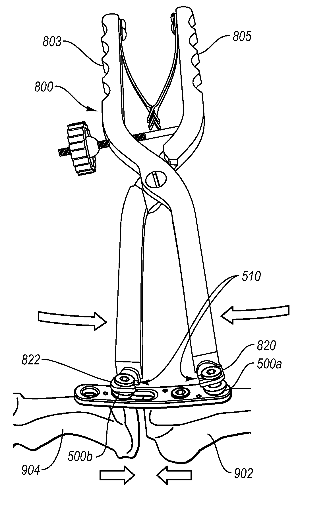
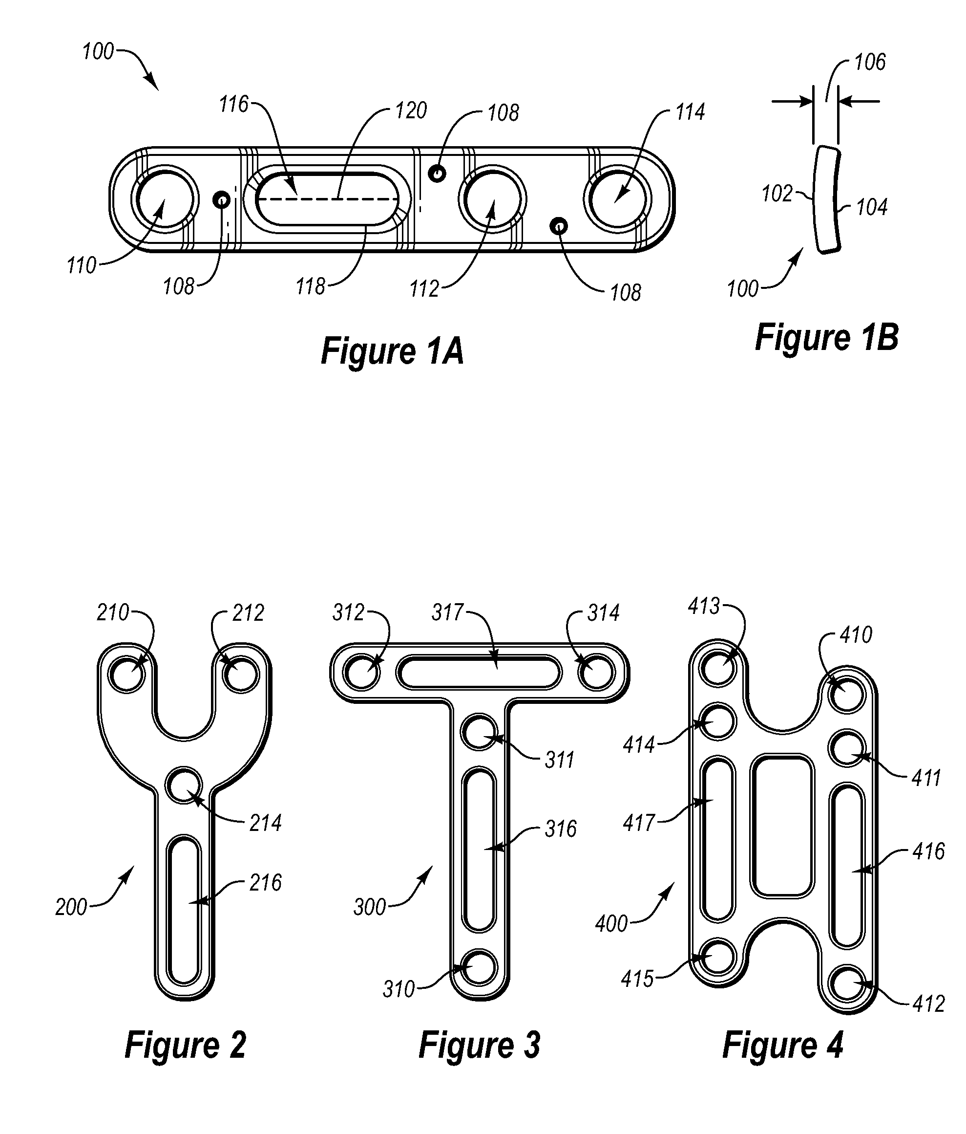
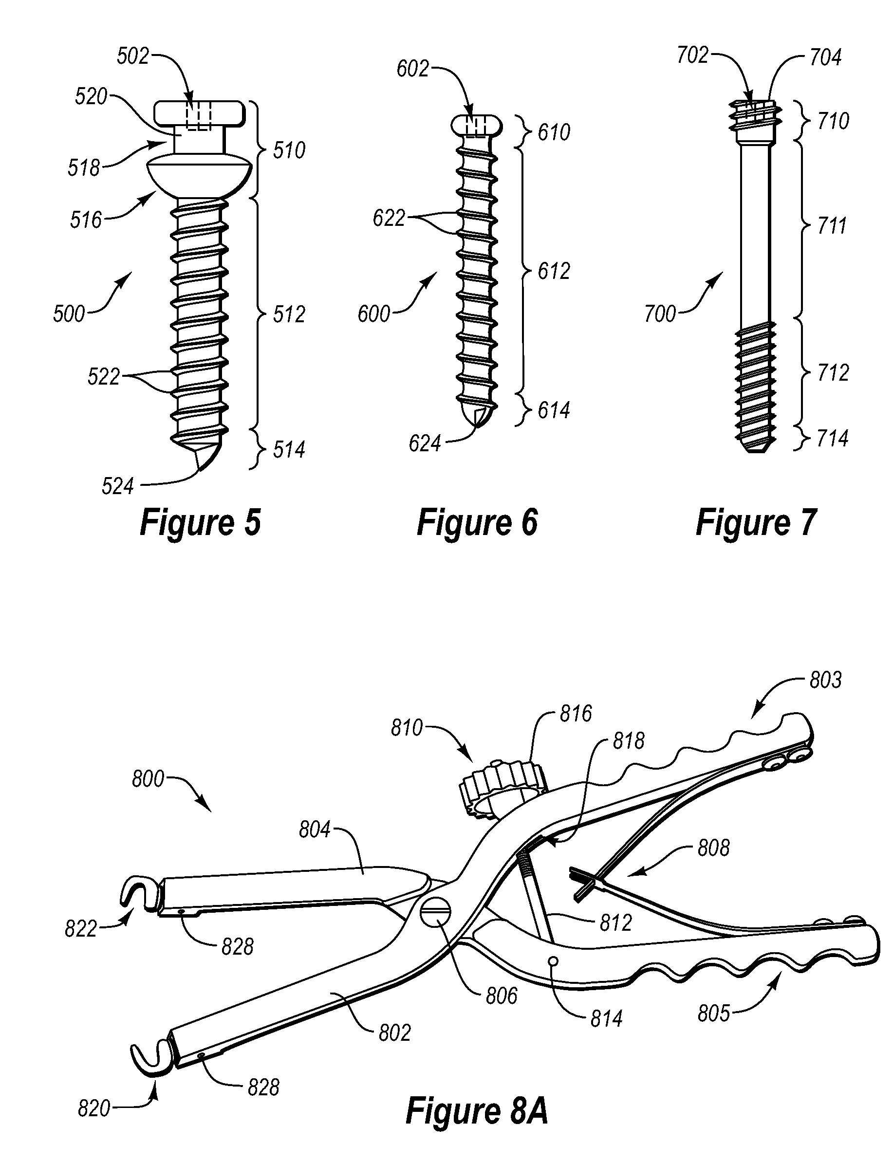
The present invention provides a system, method, and apparatus for correcting bone discontinuities with great versatility. The invention includes a compression plate kit that allows for manual compression control of bone discontinuities, as well as a compression clamp that can be used to pull bone portions together. The kit also includes reduction fasteners that can be inserted into a bone plate and an elongated slide channel to compress bone discontinuities. The invention can efficiently and accurately correct various types of bone injury.

Problems solved by technology

Such changes to the shape of the bone can alter the mechanics of the bone in a manner that could weaken or result in changes to the biomechanics of the patient's body.
Additionally, such spacing can result in abnormal growth in the bone that can create additional complications.
Unfortunately, conventional compression plates tend to suffer from a number of drawbacks.
For example, the length of conventional compression slots, and thus the amount of compression provided thereby, is limited by the size and shape of the head of the screw being used therewith.
Furthermore, controlling the exact amount of compression or spacing between bone portions using conventional compression plates can be difficult.

Method used


Image

  • Methods for repairing bone discontinuities
  • Methods for repairing bone discontinuities
  • Methods for repairing bone discontinuities

Examples


Embodiment Construction

[0033]Implementations of the present invention provide systems, methods, and apparatus that provide a great deal of functional versatility in correcting bone discontinuities. For example, one or more implementations of the present invention includes a compression plate kit that allows for manual compression control of a bone discontinuity for improved repair of fractures, fusions, and other bone discontinuities. Additionally, one or more implementations of the present invention includes compression plate kits that allow for the compression of larger gaps between bones. Accordingly, implementations of the present invention can allow for efficient and accurate correction of various different types of bone injury.

[0034]For instance, according to one implementation of the present invention, a compression plate kit allows a practitioner to not only manually control the compression and reduction of a bone discontinuity, but to also feel and / or see the amount of compression. The ability to...


PUM


Abstract

A compression plate kit that allows for manual compression of a bone discontinuity includes a bone plate, two or more reduction screws, and a compression clamp. The compression clamp can include engagement members configured to engage the reduction screws, thereby allowing a practitioner to compress a bone discontinuity by manually closing the compression clamp. One or more implementations of a kit of the present invention can provide a practitioner with physical or tactile feedback during the compression of a bone discontinuity, and thus, provide the practitioner with the ability to better control the compression and spacing of bone portions during a reduction.

Description

BACKGROUND OF THE INVENTION[0001]1. The Field of the Invention[0002]The present invention relates generally to a kit for repairing bones. More specifically, the invention relates to a compression plate kit configured to permit manual reduction of bone discontinuities and methods of using the compression plate kit for repairing bone discontinuities.[0003]2. Background and Relevant Art[0004]Bones perform a variety of important functions, including support, movement, protection, storage of minerals, and formation of blood cells. To help ensure that bones can perform these important functions, and to reduce pain or correct disfigurement, injured bones should be promptly and properly repaired. In repairing fractured or otherwise injured bones, it is common for a practitioner to use a fixation device that both reinforces the bone and keeps it properly aligned during healing. One common type of fixation device is a bone plate.[0005]To use a bone plate to repair a discontinuity of a bone, a...

Claims


Application Information

Patent Timeline
Patent Type & Authority Patents(United States)
IPC IPC(8): A61B17/88A61F2/08A61B17/04A61B17/84A61B17/66A61B17/80
CPCA61B17/7079A61B17/8014A61B17/8061A61B17/861A61B17/8866A61B17/863A61B2017/00004
Inventor SCHELLING, CRAIG
Owner WRIGHT MEDICAL TECH
Learn More