Root-Cause Analysis System And Associated Methods

Inactive Publication Date: 2010-06-03
LOCKHEED MARTIN CORP
View PDF9 Cites 24 Cited by
  • Summary
  • Abstract
  • Description
  • Claims
  • Application Information

AI Technical Summary

Benefits of technology

[0021]It can be seen that the present invention has a multitude of benefits, including enabling staff reductions, accelerating repairs, increasing the effec

Problems solved by technology

Such indicators can have been tripped by, for example, sensors downstream of an

Method used


Image

  • Root-Cause Analysis System And Associated Methods
  • Root-Cause Analysis System And Associated Methods
  • Root-Cause Analysis System And Associated Methods

Examples


Example

[0032]A description of the preferred embodiments of the present invention will now be presented with reference to FIGS. 1-9.

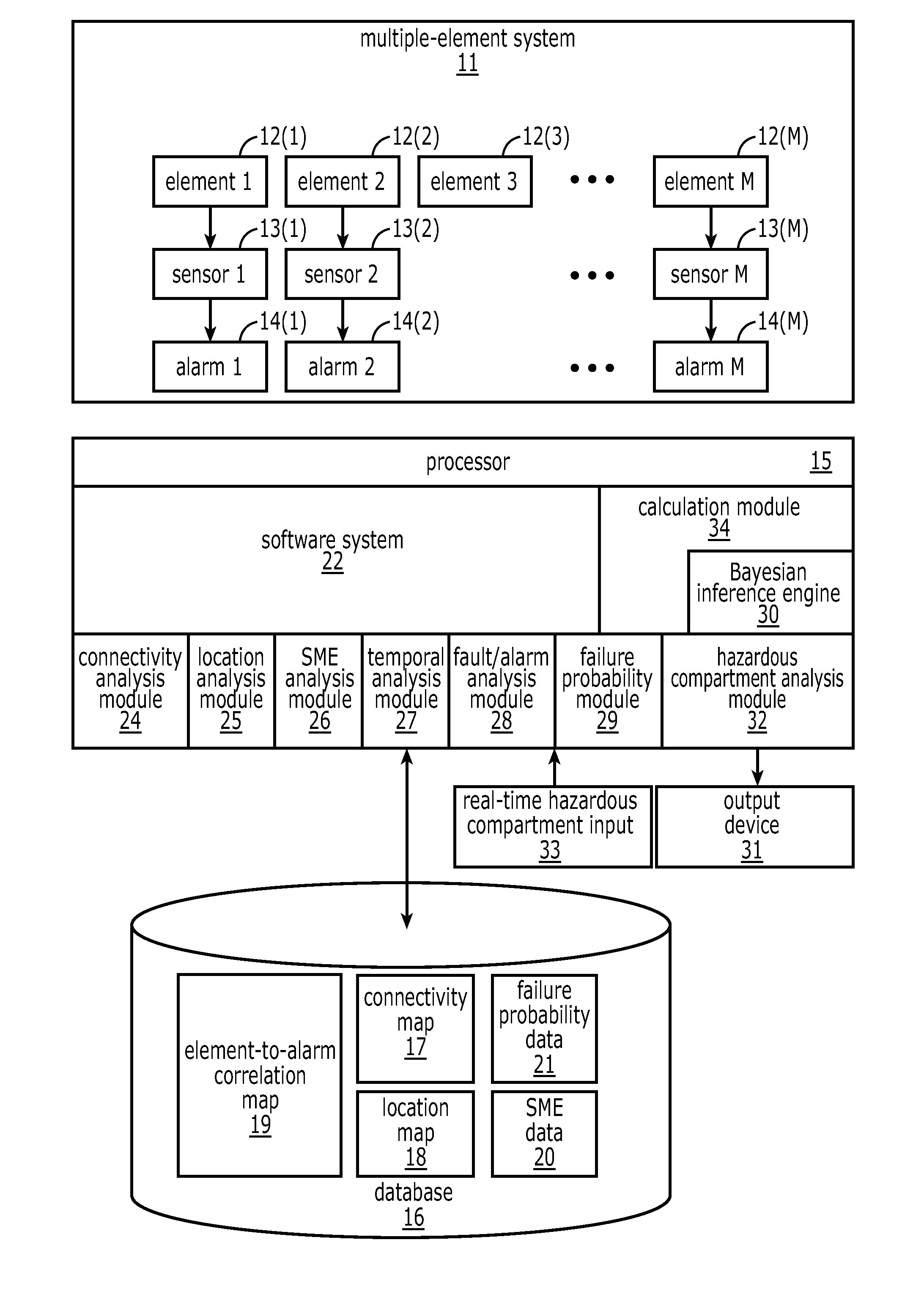
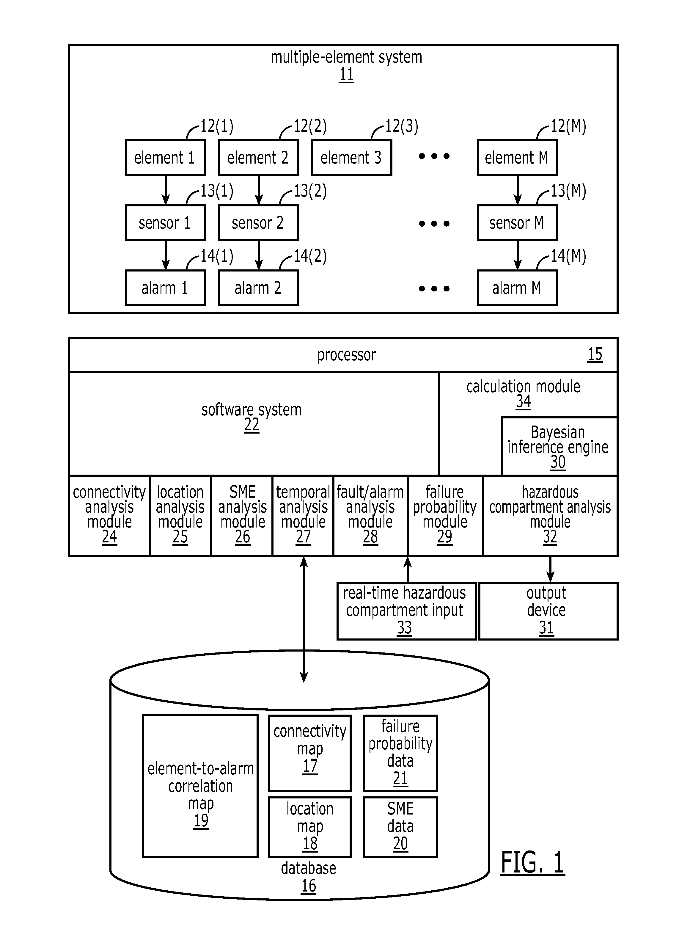
[0033]In an exemplary embodiment, not intended as a limitation on the invention, a system 10 (FIG. 1) and method 100 (FIGS. 2A,2B) are provided for identifying the most likely source(s) of problems on a ship. One of skill in the art will recognize that the system and method are equally applicable to performing root-cause analysis on any complex, multi-element system 11.

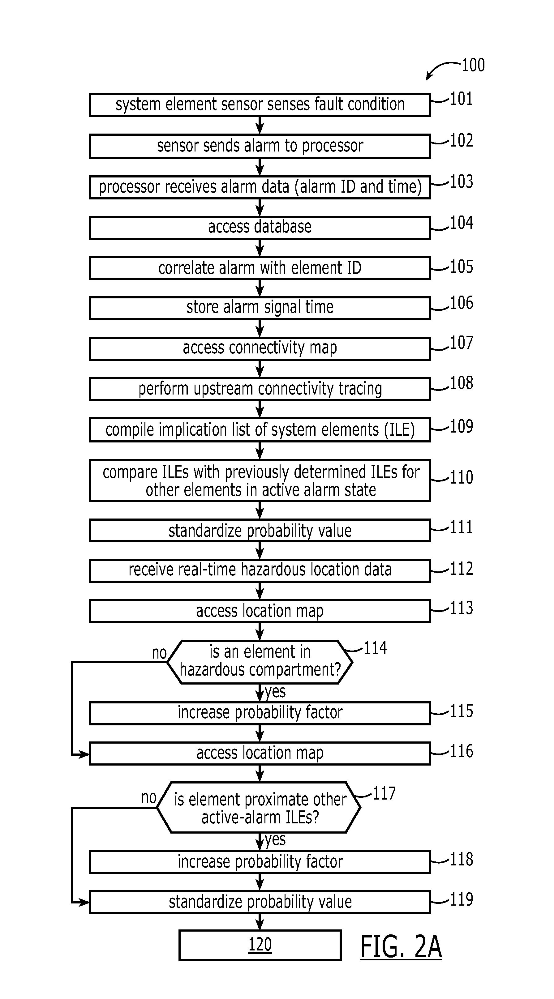
[0034]An exemplary multi-element system 11 comprises element 112(1) through element M 12(M) (see, for example, the element list 23 of FIG. 5). At least some of the elements 12(1)-12(M) are in signal communication with a respective sensor 13(1)-13(M). Each sensor 13(1)-13(M) is adapted to issue an alarm signal 14(1)-14(M) (block 102) when a respective element 12(1)-12(M) is sensed to be in a fault condition (block 101). Not all elements in the multi-element system 11, however, are typically equipp...


PUM


Abstract

A method for determining a root cause of a problem in a multiple-element system includes correlating an incoming alarm signal with an element x in a multiple-element system and accessing an implication list comprising a list of all elements upstream of element x. At least one element on the implication list is weighted with data relating to the at least one element. Taking into account the weighting step, a probability is calculated that an element on the implication list comprises a most-probable root cause of the subsequent alarm signal. The identified most-probable root cause of the incoming alarm signal is output.

Description

CROSS-REFERENCE TO RELATED APPLICATIONS[0001]This application claims priority to provisional patent application 61 / 117,651, filed Nov. 25, 2008.BACKGROUND OF THE INVENTION[0002]1. Field of the Invention[0003]The present invention relates to systems and methods for determining a root cause of a problem in a multi-element system.[0004]2. Description of Related Art[0005]When a problem arises in a large system comprising a large number of elements, a multiplicity of indicators can be triggered. Such indicators can have been tripped by, for example, sensors downstream of an actual, root cause of the problem, thereby potentially masking the real problem.[0006]An exemplary, non-limiting example comprises a large, automated naval ship. Particularly in a situation in which staffing has been reduced, it is important to provide an automated process for determining a root cause of an indicated problem in the ship. Other examples, also not intended as limitations, could comprise multi-element el...

Claims


Application Information

Patent Timeline
IPC IPC(8): G06F11/07G06N5/02
CPCG06F11/0739G06N5/042G06F11/079G06F11/0784
Inventor HARRISON, GREGORY A.NELSON, HAROLD W.HALL, ROSSINGRAHAM, LORIE R.
Owner LOCKHEED MARTIN CORP
Why Eureka
Try Eureka