Supercharge Your Innovation With Domain-Expert AI Agents!

Circuit for processing sound signals

a technology for processing circuits and sound signals, applied in the direction of tone control, tone control, manual operation of tone/bandwidth control, etc., can solve the problem of audible loss in the quality of the processed sound signal, and achieve the effect of improving the quality of the sound signal

Active Publication Date: 2012-04-24
GEBR FREI
View PDF2 Cites 3 Cited by
  • Summary
  • Abstract
  • Description
  • Claims
  • Application Information

AI Technical Summary

Benefits of technology

[0004]It is therefore an object of the invention to provide a circuit for processing sound signals which is capable of improving the quality of sound signals.
[0009]By integrating the dynamic circuit with the equalizing filter, or EQ filter, very fine corrections in the sound signal can be attained. In addition, the entire sound characteristics can be processed better and simpler while also improving the quality.
[0012]In comparison with a conventional structure with dynamic filters, where typically only a single filter is employed, the equalizing filter with compressor circuit can be better controlled over the adjustable frequency range.

Problems solved by technology

Splitting and combining can break up the signal and cause an audible loss in quality of the processed sound signal.

Method used


Image

  • Circuit for processing sound signals
  • Circuit for processing sound signals
  • Circuit for processing sound signals

Examples


Embodiment Construction

[0022]Preferred embodiments of the present invention will now be described in more detail with reference to the appended drawings.

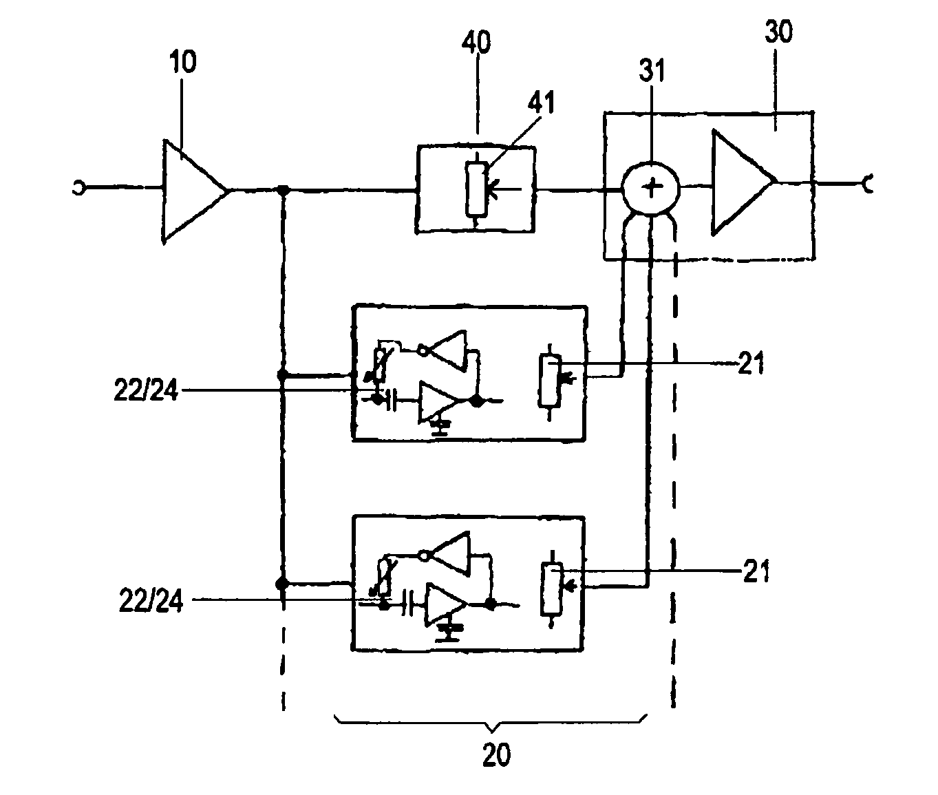
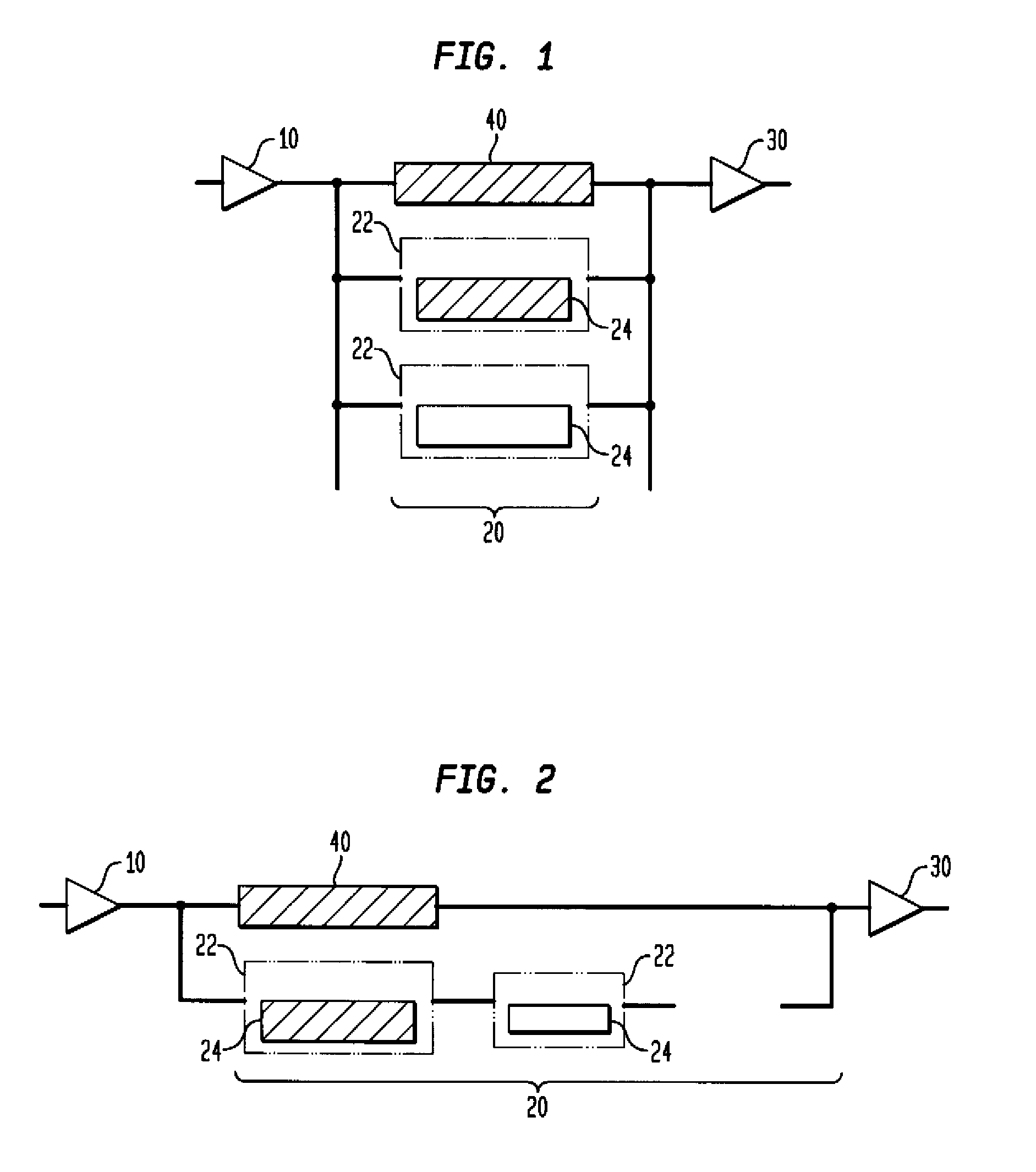
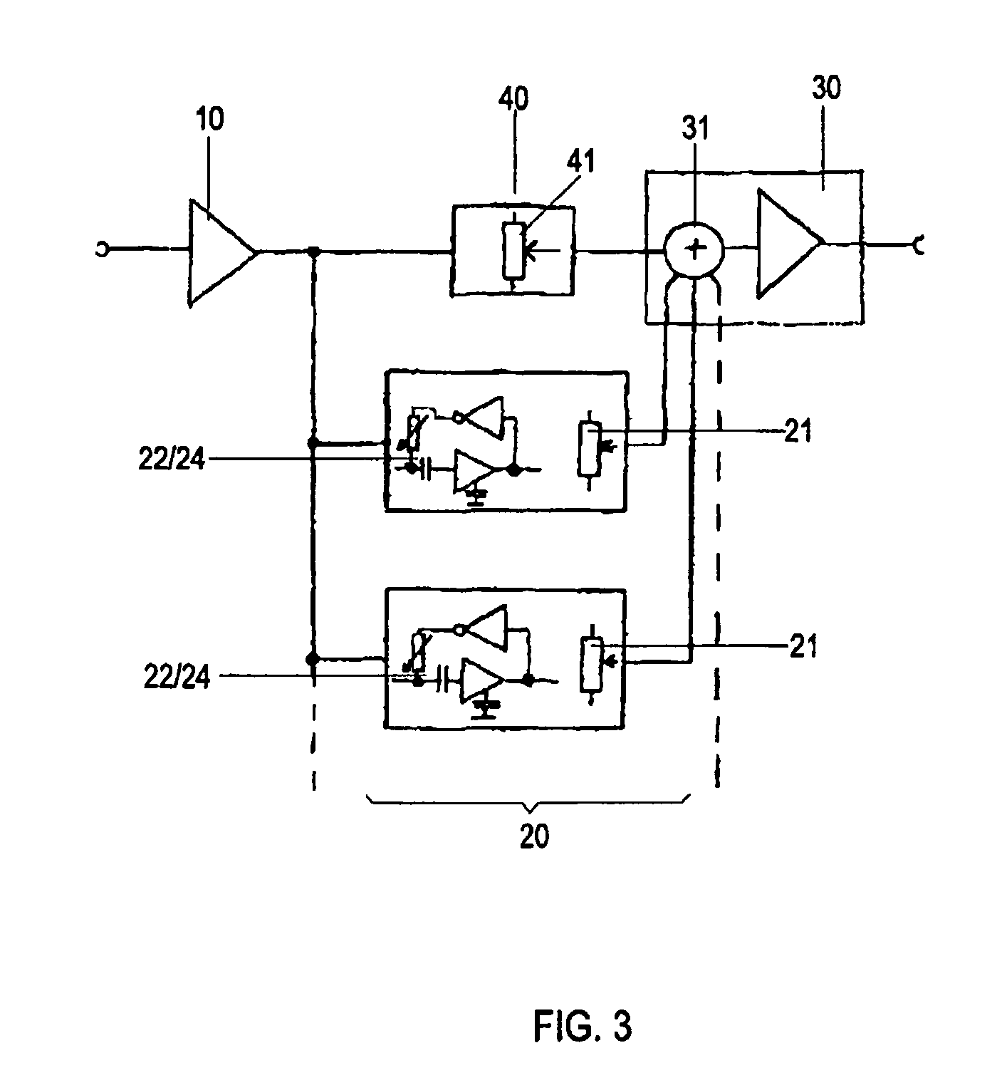
[0023]FIGS. 1 and 2 show block diagrams of corresponding embodiments of the circuit for processing sound signals according to the present invention. In accordance with the circuit described above with reference to FIG. 4, the circuit includes a signal processing device as a secondary path 20 between an input amplifiers 10 and output amplifier 30. Preferably, the output amplifier 30 also includes an adder which combines the various signal elements supplied by the signal processing device representing the secondary path 20.

[0024]Unlike the circuit shown in FIG. 4, the signal processing device depicted in FIG. 1 is implemented as a secondary path 20 and constructed of circuits with filters 22 which are connected in parallel. The circuits pass the amplified input signal from the input amplifier 10 only in certain frequency ranges, and include dynamic circuits...


PUM


Abstract

A circuit for processing sound signals includes an input amplifier for amplifying an input signal, wherein the amplified input signal is supplied to an output amplifier unchanged via a primary path configured as a bypass line and processed via one or several secondary paths configured as a circuit for processing the amplified input signal for amplifying and outputting the processed signal, wherein respective signal portions of the amplified input signal, which are supplied to the output amplifier via the primary path and the secondary path(s), can each be adjusted with an adjusting device, and wherein the secondary path includes a corresponding equalizing filter for filtering a corresponding frequency range with a dynamic circuit for optionally dynamically changing frequency, amplitude and phase depending on the signal and concurrent with a static control.

Description

BACKGROUND OF THE INVENTION[0001]The invention relates to a circuit for processing sound signals.[0002]Known circuits for processing sound signals are, for example, multiband compressors. This type of circuit, which is shown in the example of FIG. 4, has a signal processing device 20 arranged between an input amplifier 10 and an output amplifier 30. The signal processing device 20 is constructed of a parallel connection of circuits with filters 22a, 22b, 22c, which pass the amplified input signal received from the output amplifier 10 only in defined frequency ranges and includes dynamic circuits 24a, 24b, 24c which are connected after the filters 22a, 22b, 22c and represent compressors for further compressing the defined frequency range.[0003]As shown in FIG. 4, the filters 22a, 22b, 22c are, for example, a low pass filter 22a, a bandpass filter 22b, and a high pass filter 22c. When using a conventional multiband compressor, the amplified input signal is completely split by the corr...

Claims


Application Information

Patent Timeline
IPC IPC(8): H03G5/00H03F99/00
CPCH03G5/04H03G5/025
Inventor JAMBOR, DIRK T.BUTZ, HELMUT
Owner GEBR FREI
Features
  • R&D
  • Intellectual Property
  • Life Sciences
  • Materials
  • Tech Scout
  • Unparalleled Data Quality
  • Higher Quality Content
  • 60% Fewer Hallucinations
Learn More