
Wig and method of making the same

a technology of wigs and wigs, applied in the field of wigs, can solve the problems of poorer appearance of wigs and wig wearing, inability to contact with the wearer's forehead, and inability to achieve the effect of preventing the generation of wrinkles, and enhancing the rigidity and shape retention of ultra thin front portions

Active Publication Date: 2012-05-01
UNIHAIR COMPANY LIMITED
View PDF10 Cites 1 Cited by
  • Summary
  • Abstract
  • Description
  • Claims
  • Application Information

AI Technical Summary

Benefits of technology

The design effectively prevents curling and wrinkling of the front edge, ensuring a close and secure fit to the wearer's head, maintaining appearance and concealing the hairline, even with repeated use.

Problems solved by technology

As one of the problems upon wearing such a wig, it is likely that a front edge of the wig is visible as a line at the wearer's frontal of head upon wearing the wig, resulting in exposure of the wig wearing to bystanders around.
In this case, contact with the wearer's head may deteriorate, and it causes poorer appearance of the wig and exposure of wig wearing.
The wig, described in Japanese Patent Number 2545240 and Japanese Patent Number 2549553, retains properly the wig base shape by a shape retention member, but contact with the wearer's forehead is not necessarily improved, in case the front edge of the wig base is curled up or the like.

Method used


Image

  • Wig and method of making the same
  • Wig and method of making the same
  • Wig and method of making the same

Examples


example

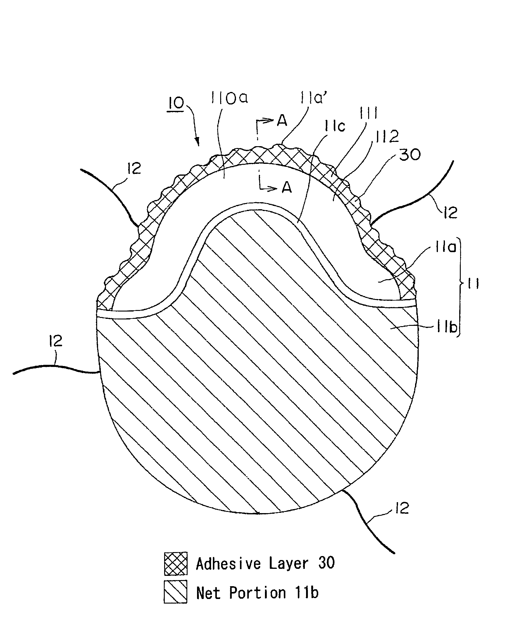
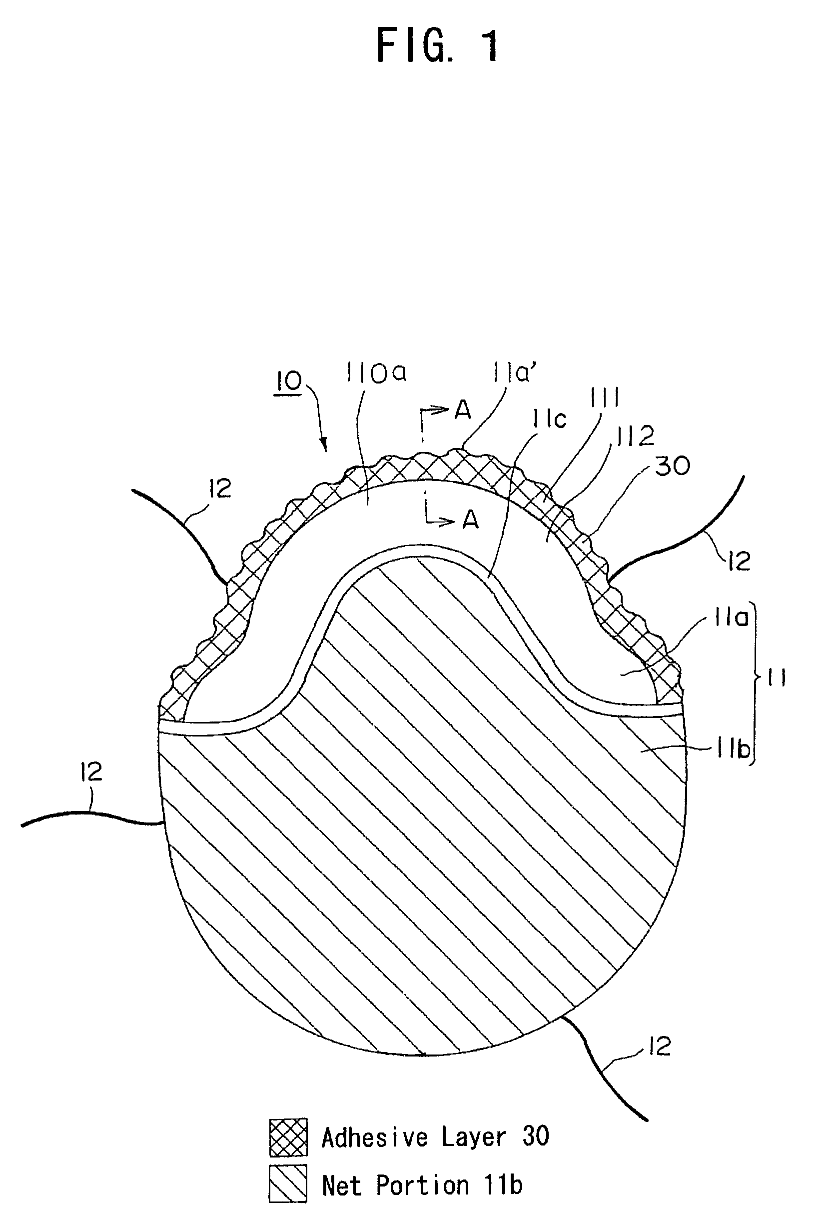
[0120]Bending rigidity of the front portion 11a fixed to a shape retention net 23 was measured. As a Comparative Example, likewise the above-mentioned front portion 11a, the front portion comprising only the artificial skin not including the shape retention net 23 was manufactured. As the measurement of bending rigidity, the whole sample of the artificial skin was bent as the sample at constant speed to an arc shape to a certain curvature, a small bend momentum accompanying it was detected, and the relationship between this bend momentum and the curvature was measured. As the measuring conditions were Distance between Chucks: 1 cm, Torque Detector: Detection of Torque of Tortion Wire (Steel Wire), Torque Sensitivity: 1.0 gf·cm (at Full Scale 10V), Curvature: ±2.5 cm×10−1, Rate of Bend Deviation: 0.5 cm×10−1 / sec, Measurement Cycle: 1 Round Trip, Sample width: 1 cm, Sample film thickness: 100-110 μm for both with and without net, Temperature: 22° C., Humidity: 60% RH.

[0121]As the resu...


PUM


Abstract

In the wig 10 provided with a wig base 11 and hair materials 12 attached to the wig base, the wig base 11 is zoned in its front portion 11a to an artificial skin portion 110a from a virtual hairline of the wearer's forehead portion toward a top portion and to a net pattern 11b connected thereto, the artificial skin portion is made of a synthetic resin film integrated with a shape retention net, provided with a front edge region 111 of the pre-determined width from a front edge 11a′ positioned on the wearer's virtual hairline toward inside and with a rear region 112 connected to the front edge region, and the front edge region 111 is bent to a sharper inclination than the wearer's corresponding head outline, giving a curved ridge line, resulting in an arc-shaped warp up prevention structure.

Description

TECHNICAL FIELD[0001]This invention relates to a wig covering at least a part of the wig wearer's head from its frontal of the head toward back of the head, and a method of making the same.BACKGROUND ART[0002]A conventional wig for wearing on a thin haired head has a wig base comprising an artificial skin made of synthetic resin and a mesh-like net or their combination, and the wig base is formed accurately correspond to or similar appearance to the wearer's head shape, and then completed with such hair material as human or artificial hair attached thereto.[0003]As one of the problems upon wearing such a wig, it is likely that a front edge of the wig is visible as a line at the wearer's frontal of head upon wearing the wig, resulting in exposure of the wig wearing to bystanders around. Therefore, several methods have been proposed recently to prevent wig exposure by making the border between the forehead skin and the wig hardly visible.[0004]In order to solve the problem, a conventi...

Claims


Application Information

Patent Timeline
Patent Type & Authority Patents(United States)
IPC IPC(8): A41G3/00
CPCA41G3/0041A41G3/0075A41G3/005A41G3/0025
Inventor MARUYAMA, SHIN-ICHISATO, TAKASHIKONDO, YASUHIRO
Owner UNIHAIR COMPANY LIMITED
Learn More