Apparatus for centrifugal casting under vacuum

a technology of centrifugal casting and vacuum, which is applied in the direction of foundry molds, foundry cores, foundry moulding apparatus, etc., can solve the problems of shrinking, shrinking, shrinking, and forming cold runs on both machines, and achieves the effect of improving quality

Active Publication Date: 2012-05-01
MANFRED RENKEL
View PDF10 Cites 27 Cited by
  • Summary
  • Abstract
  • Description
  • Claims
  • Application Information

AI Technical Summary

Benefits of technology

[0005]It is an object of the present invention to overcome the disadvantages in the art. According to an aim of the invention there shall be provided an apparatus for centrifugal casting by which castings having a complicated geometry can be cast with an improved quality. According to a further aim of the invention by the proposed apparatus a production of high-quality castings made of titanium aluminides shall be possible.

Problems solved by technology

However, both machines are not suitable for carrying out a centrifugal casting process under vacuum.
However, when producing castings from titanium aluminides or titanium grade 2 having thin walls and a complex geometry, e.g. shrouded turbine blades or turbo charges wheels, one is encountered with several problems, like the formation cold-runs, hot tears, shrinkholes, pores, voids and the like.

Method used


Image

  • Apparatus for centrifugal casting under vacuum
  • Apparatus for centrifugal casting under vacuum
  • Apparatus for centrifugal casting under vacuum

Examples


Embodiment Construction

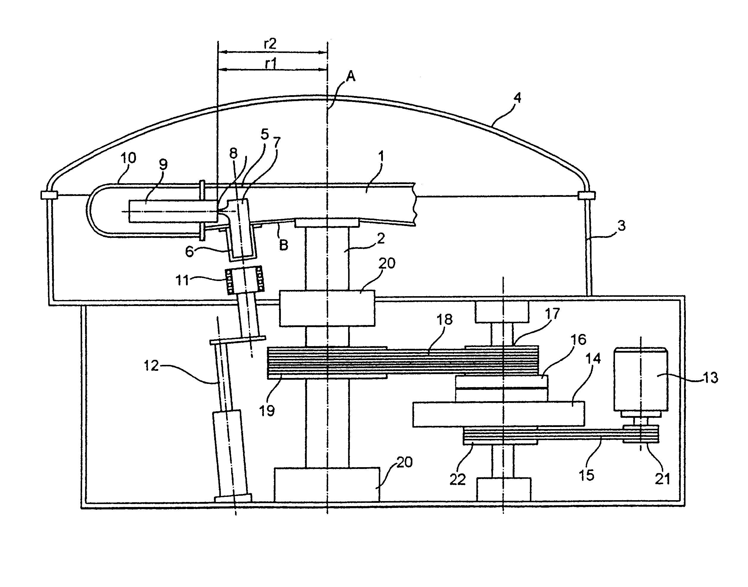
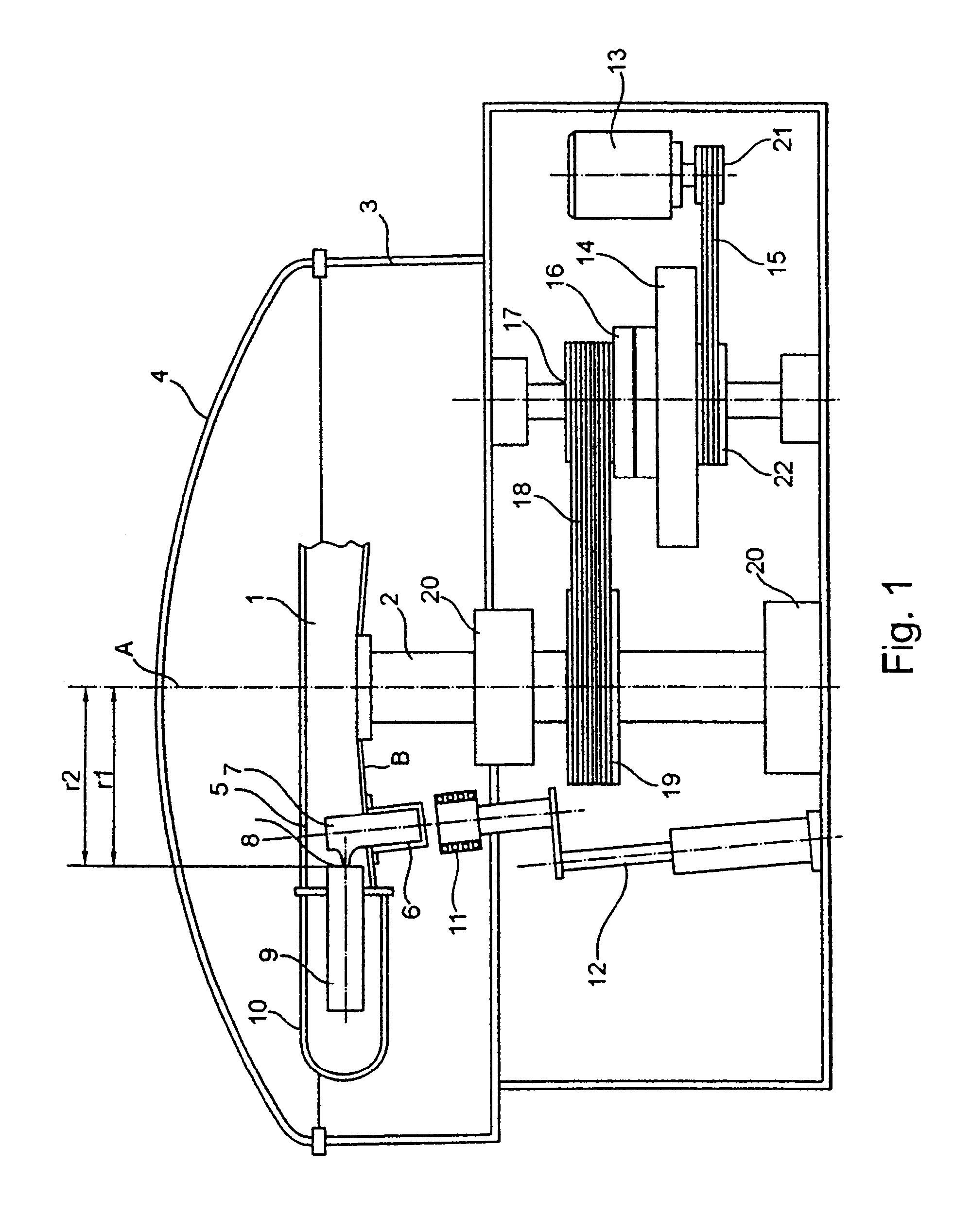
[0027]FIG. 1 shows a first apparatus for centrifugal casting. A rotor 1 has a shaft 2 which extends vertically therefrom. The shaft 2 is rotatable around an axis A. The rotor 1 is accommodated within a housing 3. A lid 4 of the housing 3 can be opened.

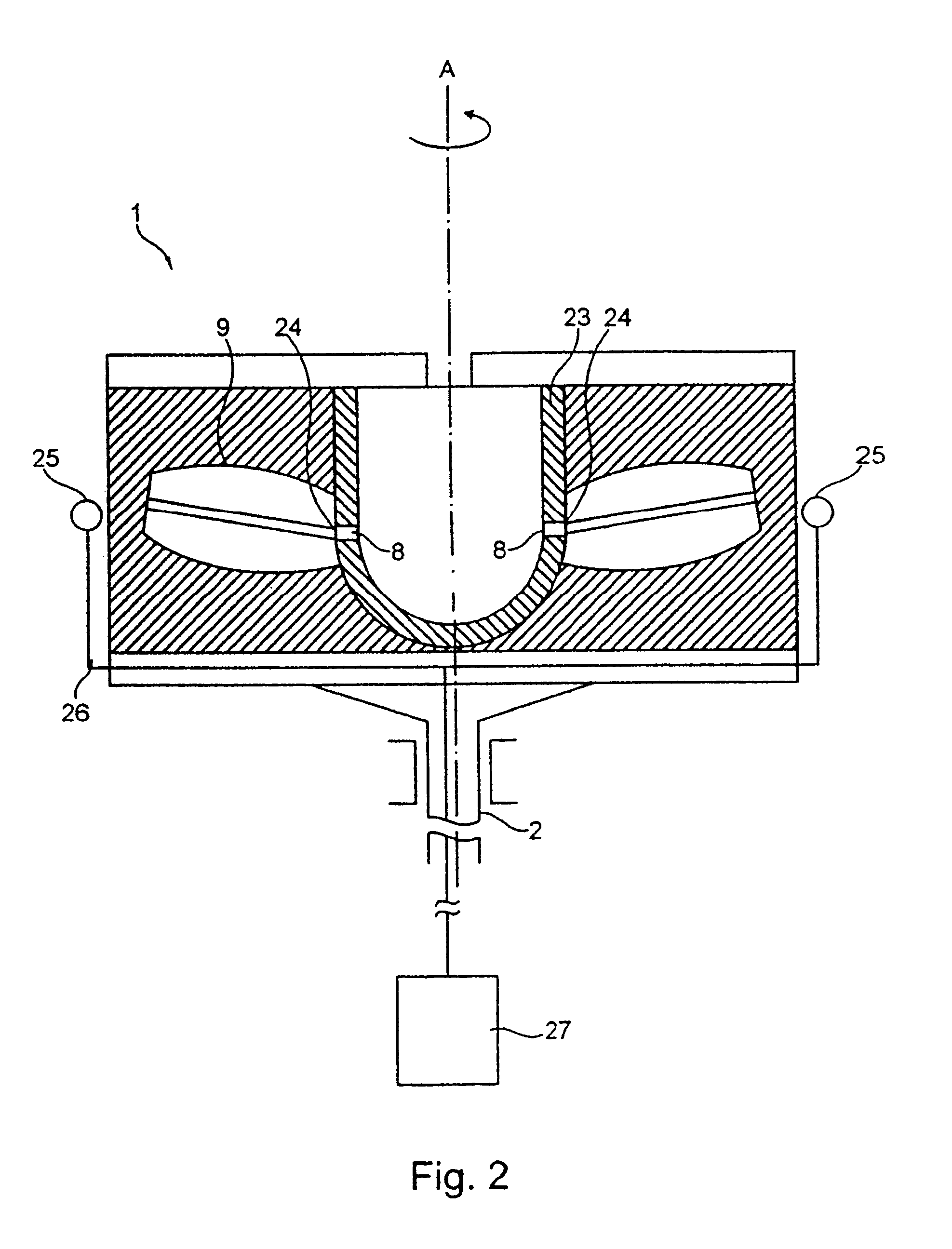
[0028]The rotor 1 may comprise several arms 5 which extend in a radial direction therefrom. In a bottom B of each arm 5 there is provided an opening which is sealed in gas-tight manner by a first crucible 6 extending the vertical direction from the bottom B. The first crucible 6 may be made of a heat resistant material like alumina, silica-glass or the like. Within the first crucible 6 there is accommodated a second crucible 7 which may be made again of a heat resistant material like alumina, Y2O3, magnesia and the like. The second crucible 7 also extends beyond the bottom B of the arm 2. The second crucible 7 has in an upper section thereof a radial outwardly protruding outlet opening 8 which is distanced from the axis A with a second...


PUM

PropertyMeasurementUnit
radial distanceaaaaaaaaaa

Abstract

An apparatus for centrifugal casting under vacuum includes a rotor having a shaft extending in an essentially vertical direction and being rotatable around an axis defined by the shaft. The rotor has at least one mold, at least one crucible, and a gas-tight housing in which the mold and the crucible are accommodated. The apparatus also includes a vacuum source to create a vacuum in the housing, a heating device that melts a metal, a drive device that drives the shaft in order to rotate the rotor, and an auxiliary acceleration device configured to generate a force to further rotate the rotor to overcome a moment of inertia of the rotor. The auxiliary acceleration device includes a jet propulsion and / or at least one pushing actuator accelerating the resting rotor.

Description

BACKGROUND OF THE INVENTION[0001]The invention pertains to an apparatus for centrifugal casting under vacuum, in particular for the production of castings made of titanium aluminides.[0002]RU 2 056 971 C1 as well as GB 647 019 A describe centrifugal casting machines having an auxiliary acceleration device for generating a force to overcome a moment of inertia of a rotor. However, both machines are not suitable for carrying out a centrifugal casting process under vacuum.[0003]US 2001 / 0045267 A1 describes an apparatus for centrifugal casting under vacuum. In the known apparatus a first crucible and a rotor are accommodated within a gas-tight vacuum chamber. A melt being taken up in a first crucible is poured into a second crucible or gate, respectively, which is part of the rotor which can be rotated around a vertical axis. The gate has a plurality of radial outlet openings opposite of which there are arranged inlet openings of molds extending in a radial direction. The melt being pou...

Claims


Application Information

Patent Timeline
Patent Type & Authority Patents(United States)
IPC IPC(8): B22D13/06B22D13/12
CPCB22D13/06B22D13/066B22D13/10
Inventor RENKEL, MANFRED
Owner MANFRED RENKEL
Why Eureka
Try Eureka