LED illumination device and lamp unit thereof

a technology of led illumination and lamp unit, which is applied in the direction of fixed installation, lighting and heating apparatus, light source combination, etc., can solve the problems of heat dissipation and the inability of the illumination device to obtain the desired illumination area

Inactive Publication Date: 2012-05-01
HON HAI PRECISION IND CO LTD
View PDF21 Cites 74 Cited by
  • Summary
  • Abstract
  • Description
  • Claims
  • Application Information

AI Technical Summary

Benefits of technology

[0003]The present disclosure relates to light emitting diode (LED) illumination device, and particularly to an LED illumination device and a lamp unit thereof with high heat dissipating efficiency and wide illumination area.

Problems solved by technology

Thus, the illumination device cannot obtain a desired illumination area.
In addition, heat dissipation of the LED illumination device is a problem inhibiting the application of the LED illumination device, which requires to be resolved.

Method used


Image

  • LED illumination device and lamp unit thereof
  • LED illumination device and lamp unit thereof
  • LED illumination device and lamp unit thereof

Examples


first embodiment

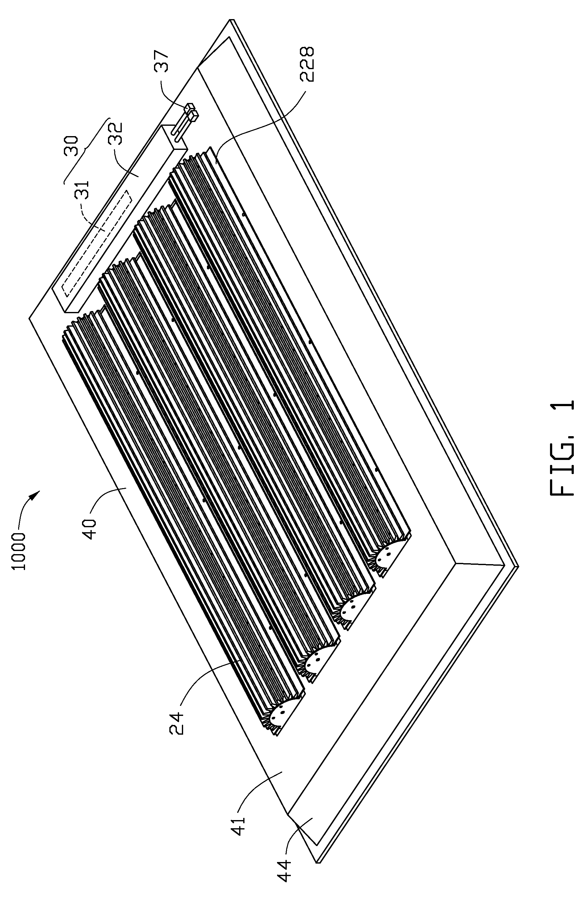
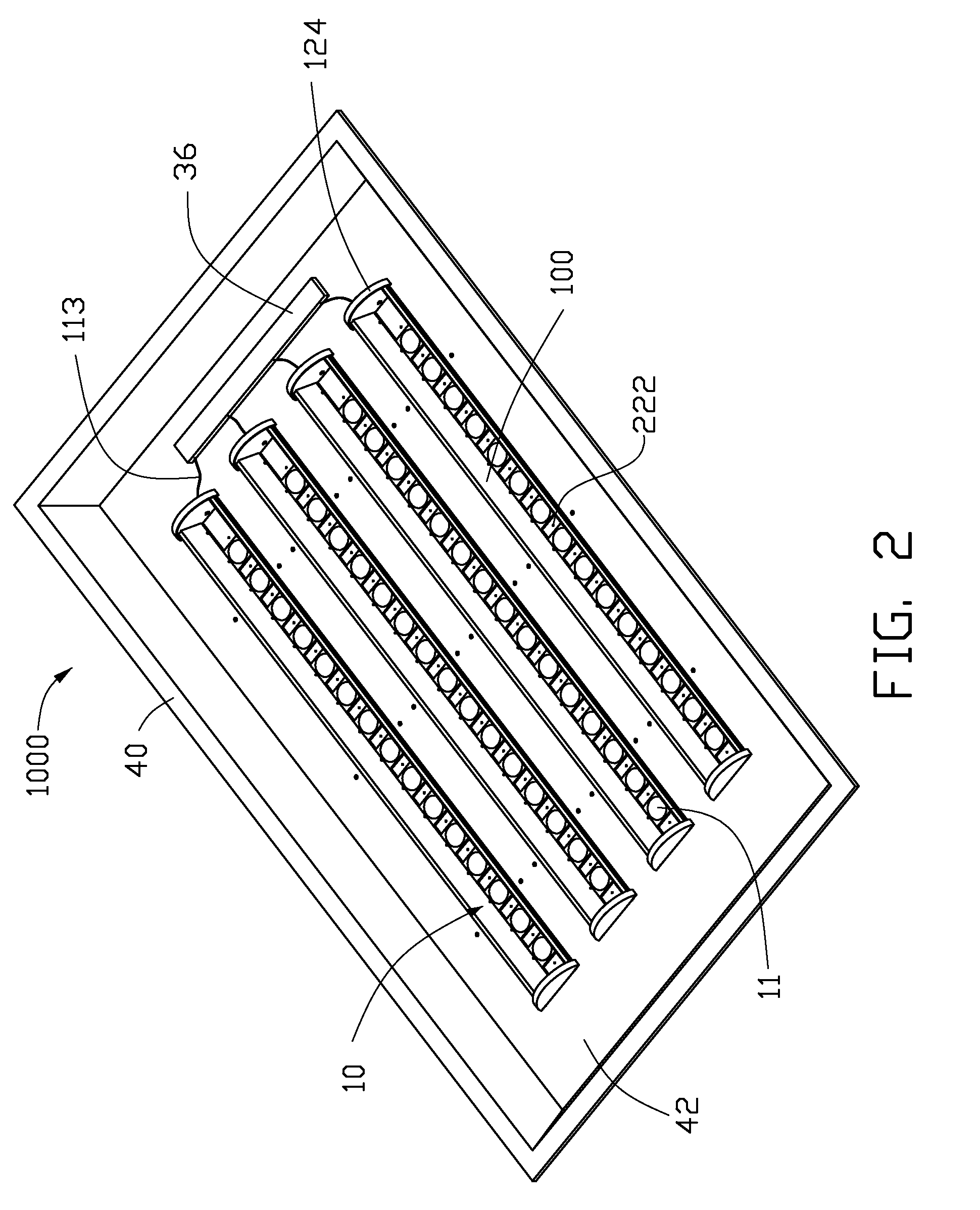
[0019]Referring to FIGS. 1-2, an LED illumination device 1000 includes a lampshade 40, a plurality of lamp units 100 and an electrical module 30 mounted on the lampshade 40. The lamp units 100 are identical to each other, and are arranged parallel to each other.

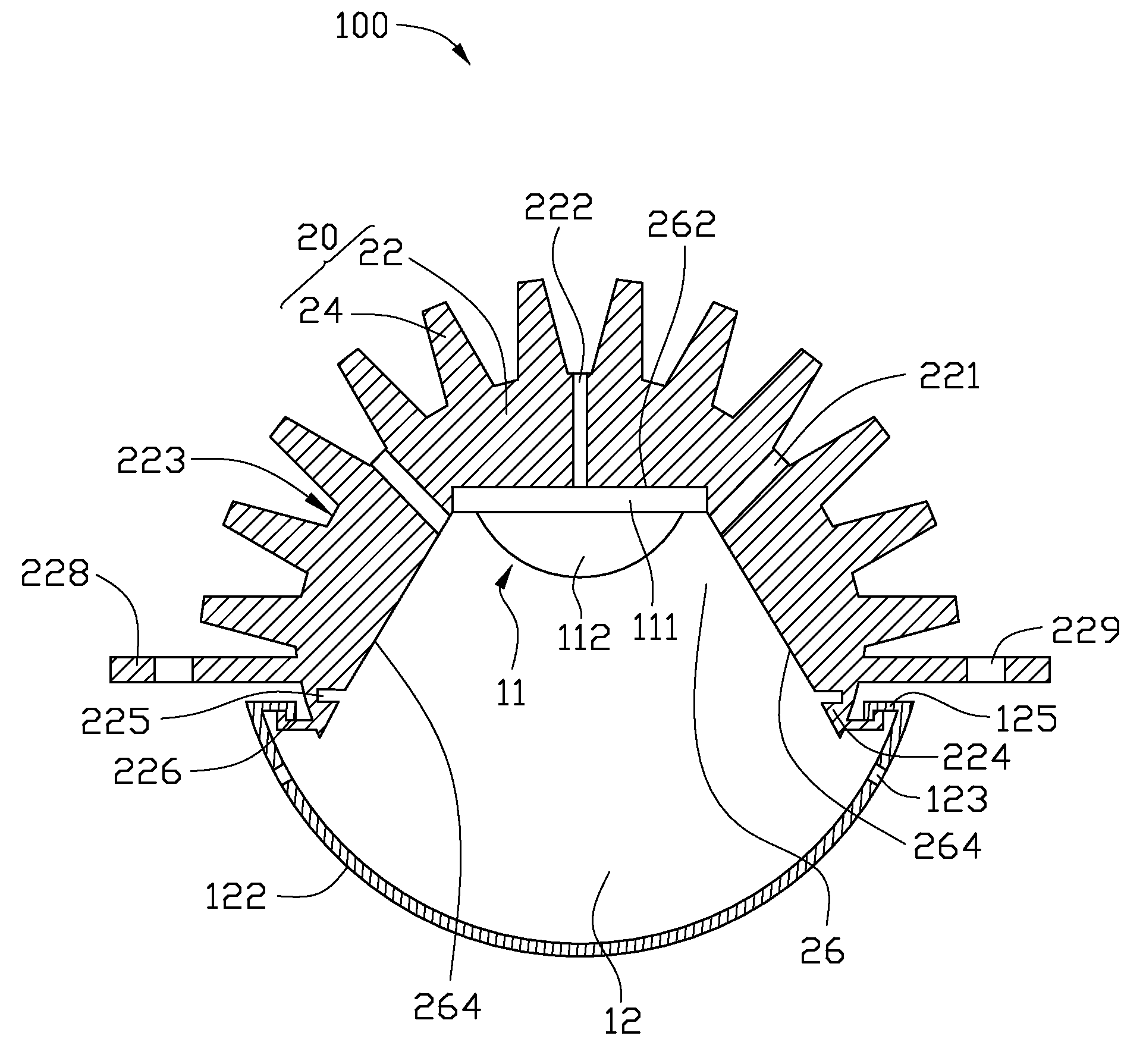
[0020]Referring to FIGS. 3-5, the lamp unit 100 includes a light-emitting module 10 and a heat sink 20 arranged above the light-emitting module 10. The light-emitting module 10 is electrically connected with the electrical module 30.

[0021]The heat sink 20 includes an elongated metal base 22 and a plurality of metal fins 24 extending from the base 22. The base 22 is substantially semicircle-shaped and defines an elongated recess 26 therein along an axial direction thereof, to thereby form an outer semicircular convex surface 223 at a top side thereof, and an opposite inner concave surface 261 at a bottom side thereof, which has a profile of a top and two lateral sides of an isosceles trapezoid. The fins 24 extend radially and...

second embodiment

[0033]Referring to FIG. 7, a lamp unit 100a of an LED illumination device is illustrated. Except the following differences, the lamp unit 100a of the present embodiment is essentially the same as the lamp unit 100 of the previous embodiment. In the present embodiment, a base 22a of a heat sink the lamp unit 100a defines axially an elongated groove 227 in a horizontal first plane 262a of a bottom thereof. Light sources 11a are received in an elongated recess 26a defined in the bottom of the base 22a and each have a substrate 111a attached to the first plane 262a. A flat heat pipe 50 is received in the groove 227 and sandwiched between the base 22a and the light sources 11a to transfer heat of the light sources 11a to the base 22a. The heat pipe 50 is well known due to its excellent heat transfer performance. The heat pipe 50 has a low thermal resistance in heat transfer due to a phase change mechanism of working fluid employed in the heat pipe 50, which improves the heat conduction ...

third embodiment

[0034]Referring to FIG. 8, a lamp unit 100b of an LED illumination device is illustrated. Except the following differences, the lamp unit 100b of the present embodiment is essentially the same as the lamp unit 100 of the previous embodiment. In the present embodiment, a base 22b of a heat sink the lamp unit 100b forms substantially a V-shaped concave surface 261b at a bottom side thereof. The concave surface 261b is constructed by two intersecting sloping planes 264b. Light sources 11b are received in an elongated recess 26b defined in the bottom side of the base 22b and symmetrically attached to the two sloping planes 264b. Each of the two sloping planes 264b of the base 22b function as a heat-absorbing surface for the light sources 11b. The base 22b defines a plurality of exchanging holes 222b through the base 22b at a joint of the two sloping planes 264b of the concave surface 261b.


PUM


Abstract

An LED illumination device includes a lampshade, and a plurality of lamp units mounted on the lampshade. Each lamp unit includes a light-emitting module having a plurality of light sources and a heat sink arranged above the light-emitting module. The heat sink includes an elongated base and a plurality of fins on the base. The base has an outer convex surface formed at a top side thereof and an opposite inner concave surface formed at a bottom side thereof. The fins extend outwardly from the convex surface of the base. The concave surface defines an elongated recess extending along an axial direction of the base. Two opposite free ends of the base are spaced from each other and cooperatively define a light emitting window below the concave surface. The light sources are received in the recess and thermally attached to the concave surface.

Description

CROSS-REFERENCE TO RELATED APPLICATION[0001]This application is related to a co-pending U.S. patent application entitled “LED ILLUMINATING DEVICE AND LAMP UNIT THEREOF” Ser. No. 12 / 478,772 and filed in the same day as the instant application. The co-pending U.S. patent application is assigned to the same assignee as the instant application. The disclosures of the above-identified application are incorporated herein by reference.BACKGROUND[0002]1. Technical Field[0003]The present disclosure relates to light emitting diode (LED) illumination device, and particularly to an LED illumination device and a lamp unit thereof with high heat dissipating efficiency and wide illumination area.[0004]2. Description of Related Art[0005]In recent years, LEDs are preferred for use in illumination devices rather than CCFLs (cold cathode fluorescent lamps) due to their excellent properties, including high brightness, long lifespan, wide color range, and etc.[0006]For an LED, about eighty percents of t...

Claims


Application Information

Patent Timeline
Patent Type & Authority Patents(United States)
IPC IPC(8): F21V29/00
CPCF21S8/02F21V29/004F21V29/006F21V29/83F21V29/777F21V29/506F21V29/507F21V29/77F21Y2101/02F21Y2103/003F21Y2111/002H01L2924/0002H01L2924/00F21Y2103/10F21Y2115/10F21Y2107/10F21Y2113/00F21K9/20F21V29/51
Inventor LIU, TAY-JIAN
Owner HON HAI PRECISION IND CO LTD
Why Eureka
Try Eureka