Method and apparatus for supporting rotor assemblies during unbalances

a technology of rotor assemblies and unbalances, applied in the direction of liquid fuel engines, vessel construction, marine propulsion, etc., can solve the problem of shaft operating above vibratory bending mode frequency, and achieve the effect of reducing the dynamic loading of gas turbine engines

Active Publication Date: 2012-05-01
GENERAL ELECTRIC CO
View PDF17 Cites 20 Cited by
  • Summary
  • Abstract
  • Description
  • Claims
  • Application Information

AI Technical Summary

Benefits of technology

[0007]In one embodiment, a method for reducing dynamic loading of a gas turbine engine is provided. The gas turbine engine includes a rotor shaft assembly including a rotor shaft, a bearing assembly, a mounting race, and a support frame, the mounting race including a spherical surface. The method includes supporting the rotor shaft on the gas turbine engine support frame with the bearing assembly, the rotor shaft including a yield portion configured to permit yielding of the rotor shaft during an imbalance operation.
[0009]In yet another embodiment, a gas turbine engine assembly includes a rotor assembly for a fan wherein the rotor assembly includes a bearing assembly coupled to a support frame, a cone shaft coupled to the bearing assembly, and a rotor shaft comprising a yield portion coupled to said cone shaft through a mounting race. The mounting race includes an upstream side, a downstream side, and a spherical surface extending therebetween. The yield portion is configured to reduce an imbalance in the rotor shaft by yielding in response to torsional and moment loads generated in the rotor shaft.

Problems solved by technology

The mechanical fuse is configured to fail during an imbalance condition of the rotor shaft, such failure causing the rotor shaft to operate above a vibratory bending mode frequency of the rotor shaft.

Method used


Image

  • Method and apparatus for supporting rotor assemblies during unbalances
  • Method and apparatus for supporting rotor assemblies during unbalances
  • Method and apparatus for supporting rotor assemblies during unbalances

Examples


Embodiment Construction

[0013]The following detailed description illustrates embodiments of the invention by way of example and not by way of limitation. It is contemplated that the invention has general application to rotatable machines such as but not limited to turbines and electrical machines in industrial, commercial, and residential applications.

[0014]As used herein, an element or step recited in the singular and proceeded with the word “a” or “an” should be understood as not excluding plural elements or steps, unless such exclusion is explicitly recited. Furthermore, references to “one embodiment” of the present invention are not intended to be interpreted as excluding the existence of additional embodiments that also incorporate the recited features.

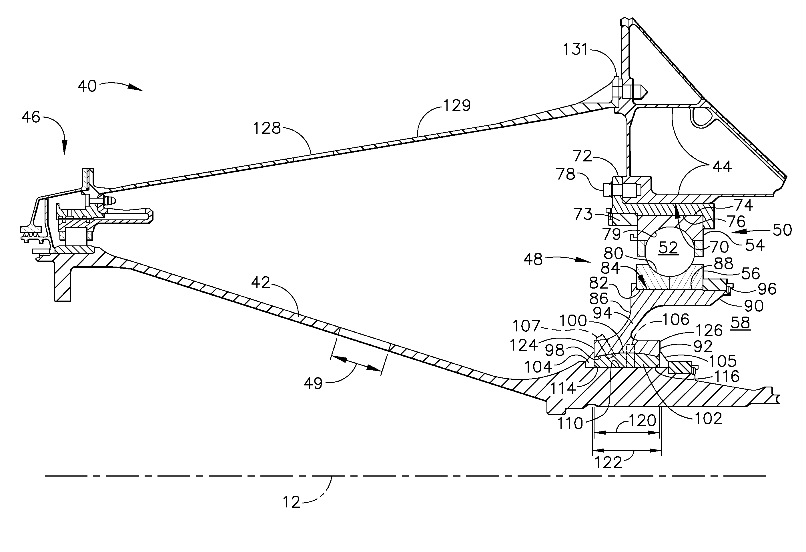
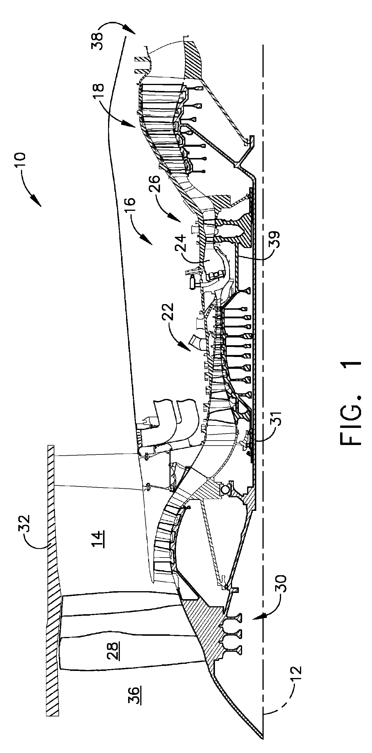
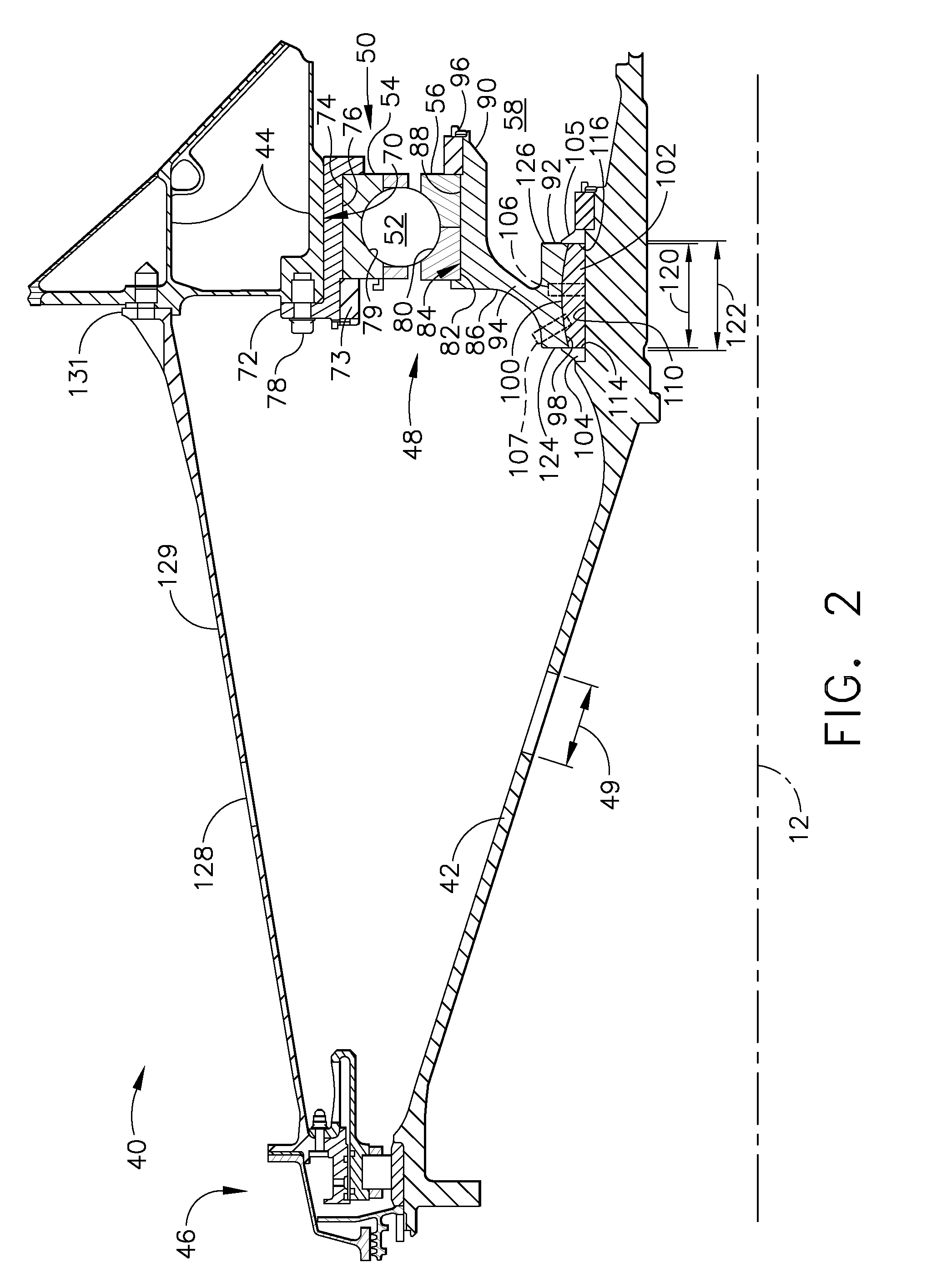
[0015]FIG. 1 is a schematic illustration of an exemplary engine assembly 10 having a longitudinal axis 12. Engine assembly 10 includes a fan assembly 14, a core gas turbine engine 16 that is disposed downstream from fan assembly 14, and a low-pressure t...


PUM


Abstract

A method and apparatus for reducing dynamic loading of a gas turbine engine is provided. The gas turbine engine includes a rotor shaft assembly including a rotor shaft, a bearing assembly, a mounting race, and a support frame, the mounting race including a spherical surface. The method includes supporting the rotor shaft on the gas turbine engine support frame with the bearing assembly, the rotor shaft including a yield portion configured to permit bending of the rotor shaft during an imbalance operation.

Description

BACKGROUND OF THE INVENTION[0001]This application relates generally to gas turbine engine rotor assemblies and, more particularly, to load reduction assemblies for gas turbine engine rotor assemblies.[0002]Gas turbine engines typically include a rotor assembly, a compressor, and a turbine. The rotor assembly includes a fan that includes an array of fan blades extending radially outward from a rotor shaft. The rotor shaft transfers power and rotary motion from the turbine to the compressor and the fan and is supported longitudinally with a plurality of bearing assemblies. Additionally, the rotor assembly has an axis of rotation that passes through a rotor assembly center of gravity. Known bearing assemblies include rolling elements and a paired race, wherein the rolling elements are supported within the paired race. To maintain rotor critical speed margin, the rotor assembly is typically supported on three bearing assemblies, one of which is a thrust bearing assembly and two which ar...

Claims


Application Information

Patent Timeline
Patent Type & Authority Patents(United States)
IPC IPC(8): F04D27/02
CPCF01D21/045F01D25/162F05D2260/941F16C19/522F16C2360/23F05D2260/79
Inventor MOLLMANN, DANIEL E.ROSS, STEVEN A.WESLING, RICHARDAGIN, THOMAS EDWARDORKISZEWSKI, CHARLES
Owner GENERAL ELECTRIC CO
Why Eureka
Try Eureka