Catalytic cracking regenerated catalyst system and gas collecting method

A regenerated catalyst and catalytic cracking technology, which is applied in the direction of physical/chemical process catalysts, chemical instruments and methods, catalyst regeneration/reactivation, etc., can solve the problems of reducing the amount of flue gas from regenerated catalysts and cannot achieve removal, and achieve the goal of overcoming water Heat deactivation problem, simple structure, effect of improving processing capacity

Active Publication Date: 2012-06-13
岳阳恒忠机械工程技术有限公司 +2
View PDF5 Cites 3 Cited by
  • Summary
  • Abstract
  • Description
  • Claims
  • Application Information

AI Technical Summary

Problems solved by technology

We can only reduce the amount of flue gas carried by the regenerated catalyst, but cannot achieve complete removal

Method used


Image

  • Catalytic cracking regenerated catalyst system and gas collecting method
  • Catalytic cracking regenerated catalyst system and gas collecting method
  • Catalytic cracking regenerated catalyst system and gas collecting method

Examples


Embodiment Construction

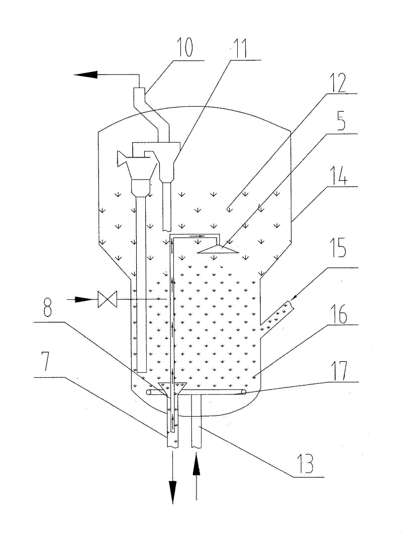
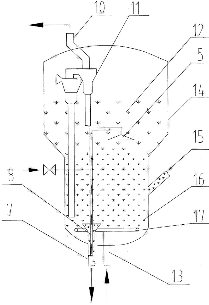
[0027] Depend on figure 1 , 2 It can be seen that the catalytic cracking regenerated catalyst system of the present invention comprises a regenerator 14 composed of a burnt air inlet 13, a regeneration standpipe 7, a standby catalyst inlet 15, a main air distributor 17, a smoke exhaust pipe 10 and a cyclone separator 11, and the The raw catalyst is fed into the regenerator 14 and forms a dense phase zone 16 and a dilute phase zone 12, wherein:

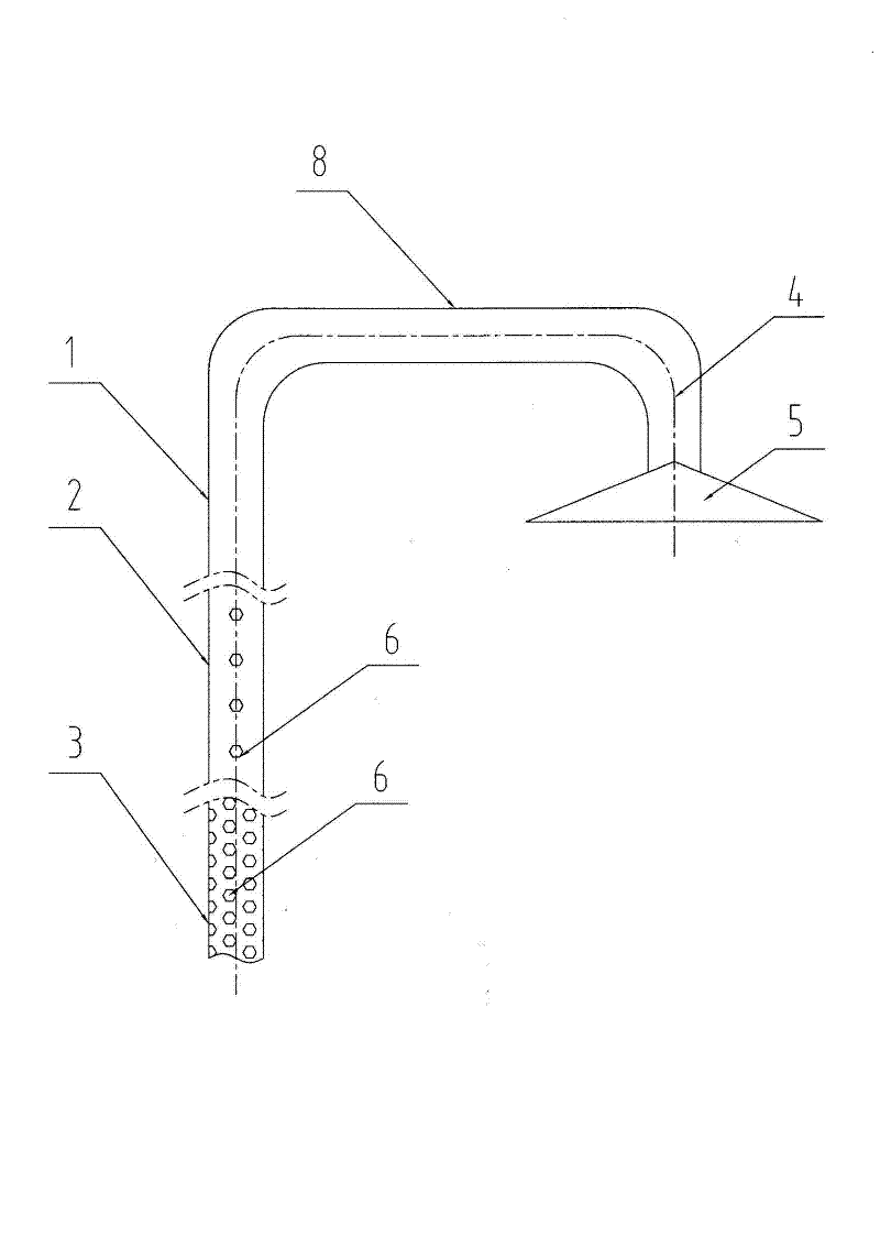
[0028] A gas collection device is fixed inside the regenerator 14 through a cantilever. The gas collection device is an air guide tube 8 with an inverted L-shaped structure, and the air guide tube 8 runs through the regeneration riser 7, the dense phase zone 16 and the dilute phase zone of the regenerator 14 as a whole. within 12;

[0029] The air guide pipe 8 includes a regeneration standpipe section 3, a dense phase section 2, a dilute phase section 1, an inverted L section 4 and a flue gas dispersion section 5, wherein the regener...


PUM


Abstract

The invention relates to a catalytic cracking regenerated catalyst system and a gas collecting method. The catalytic cracking regenerated catalyst system comprises a regenerator; a gas collecting device is arranged in the regenerator, is a gas-guide pipe with an inverted L-shaped structure and comprises a stretching regenerated vertical pipe section, a dense phase region section, a dilute phase region section, an inverted L-shaped section and a smoke dispersing section, wherein the stretching regenerated vertical pipe section is inserted into a regenerated vertical pipe; the smoke dispersing section is arranged in a dilute phase region and is bell mouth-shaped; and notches for collecting gases are uniformly arranged on the stretching regenerated vertical pipe section and the dense phase region section. According to the gas collecting method provided by the invention, smoke in a regenerated catalyst is pressed into the gas-guide pipe through the notches arranged on the gas collecting device inside the regenerated vertical pipe by mainly using a pressure difference between a dense phase region and the dilute phase region, then enters the dilute phase region through the smoke dispersing section and finally is absorbed and discharged through a cyclone separator. According to the gas collecting method, the amount of the smoke in the regenerated catalyst carried into a follow-up reaction system is effectively reduced, and the processing capacity is increased.

Description

technical field [0001] The invention relates to a catalytic cracking process in the fields of oil refining, chemical industry, etc., in particular to a catalytic cracking regenerated catalyst system and a gas collection method that reduce the catalytic cracking regenerated catalyst cycle carrying gas to a reaction system. Background technique [0002] Catalytic cracking is the most important secondary processing technology in the oil refining industry. It is one of the important conversion processes of heavy oil to light (gasoline, diesel, ethylene, propylene and other light olefins), and is currently the main source of refinery profits. . The process adopts a reaction-regeneration continuous operation mode, in which the role of the catalyst is to accelerate the chemical reaction rate. It not only increases the reaction speed of decomposition and aromatization, but also increases the reaction speed of isomerization and hydrogen transfer, so that the production capacity of t...

Claims


Application Information

Patent Timeline
Patent Type & Authority Applications(China)
IPC IPC(8): B01J38/30
Inventor 陈文良卢松坚张振江郑天佑李霞初李新华
Owner 岳阳恒忠机械工程技术有限公司
Why Eureka
Try Eureka