

Catalytic reforming recontacting process with cold capacity equalization setting
A catalytic reforming and recontacting technology, which is applied in the petroleum industry, naphtha treatment, etc., can solve the problems of complex equipment in the recontacting system, poor recontacting effect, and reduced purity of circulating hydrogen, so as to reduce steam consumption, gas Reasonable liquid separation and reduced gas phase return
- Summary
- Abstract
- Description
- Claims
- Application Information
AI Technical Summary
Problems solved by technology
Method used
Image

Examples
Embodiment 1
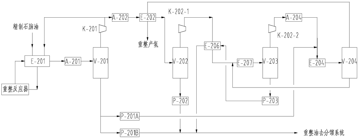
[0044] see figure 1 As shown, the catalytic reforming unit recontact process described in this embodiment, the specific situation is as follows: the reaction product from the reforming reactor is exchanged with refined naphtha and circulating hydrogen through the reforming feed heat exchanger E-201 After heating, it enters the first air cooler A-201, cools down to 35-45°C and enters the first gas-liquid separation tank V-201. The liquid phase of the first gas-liquid separation tank V-201 is divided into two circuits, one of which is boosted by the re-contact oil phase booster pump P-201A and used as re-contact oil, and mixed with the outlet stream of the fourth air cooler A-204 , into the first refrigerator E-204; the other way through the reformed oil to the booster pump P-201B of the separation system boosts the pressure and then directly enters the subsequent reformed oil fractionation system. The gas phase of the first gas-liquid separation tank V-201 directly enters the ...
Embodiment 2
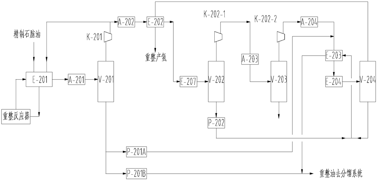
[0046] see figure 2 As shown, another catalytic reforming unit recontact process described in this embodiment is different from Embodiment 1 in that the second gas-liquid separation tank V-202 inlet is provided with a second freezer E-207, and the freezer The outlet temperature is -12°C to 4°C. The gas phase at the top of the second gas-liquid separation tank V-202 enters the primary reforming hydrogen booster K-202-1, and the liquid phase is boosted by the bottom pump P-202 of the second gas-liquid separation tank and separated from the fourth gas-liquid The liquid phase at the bottom of the tank is mixed and then enters into the precooler E-203. The outlet stream of the primary reforming hydrogen booster K-202-1 enters the third air cooler A-203 to cool to 40°C and enters the third gas-liquid separation tank V-203 for gas-liquid separation, and the gas phase enters the secondary reforming hydrogen booster Press K-202-2. Since the gas-liquid separation is carried out in t...
PUM
 Abstract
Description
Claims
Application Information