Implant which is intended to be placed in a blood vessel

a technology for implants and blood vessels, applied in the field of implants intended for blood vessels, can solve the problems of insufficient endovalves, cardiac insufficiency in the long term, and affecting the valves, so as to reduce the risk of complications and mortality

Active Publication Date: 2012-05-01
WL GORE & ASSOC INC
View PDF24 Cites 173 Cited by
  • Summary
  • Abstract
  • Description
  • Claims
  • Application Information

AI Technical Summary

Benefits of technology

[0018]An object of the invention is therefore to provide an endovalve which reduces the risk of complications and mortality when it is implanted in a coronary sinus.

Problems solved by technology

However, illnesses can affect the valves.
The problem of regurgitation leads to abnormal dilation of the ventricle which results in cardiac insufficiency in the long term.
In some cases, endovalves are not entirely satisfactory.
There is a significant risk of complications when the leaflets of the valve to be replaced extend in a region referred to as the coronary sinus, where the left and right coronary arteries open.
If the coronary arteries open below the plane which extends through the free edge of the leaflets of the valve, and if the leaflets are highly calcified, the leaflets are capable of blocking the coronary arteries, which may bring about an extended infarctus, or even death of the patient.
A solution of this type is not entirely satisfactory when the coronary arteries open below the plane delimited by the free edge of the leaflets.

Method used


Image

  • Implant which is intended to be placed in a blood vessel
  • Implant which is intended to be placed in a blood vessel
  • Implant which is intended to be placed in a blood vessel

Examples


Embodiment Construction

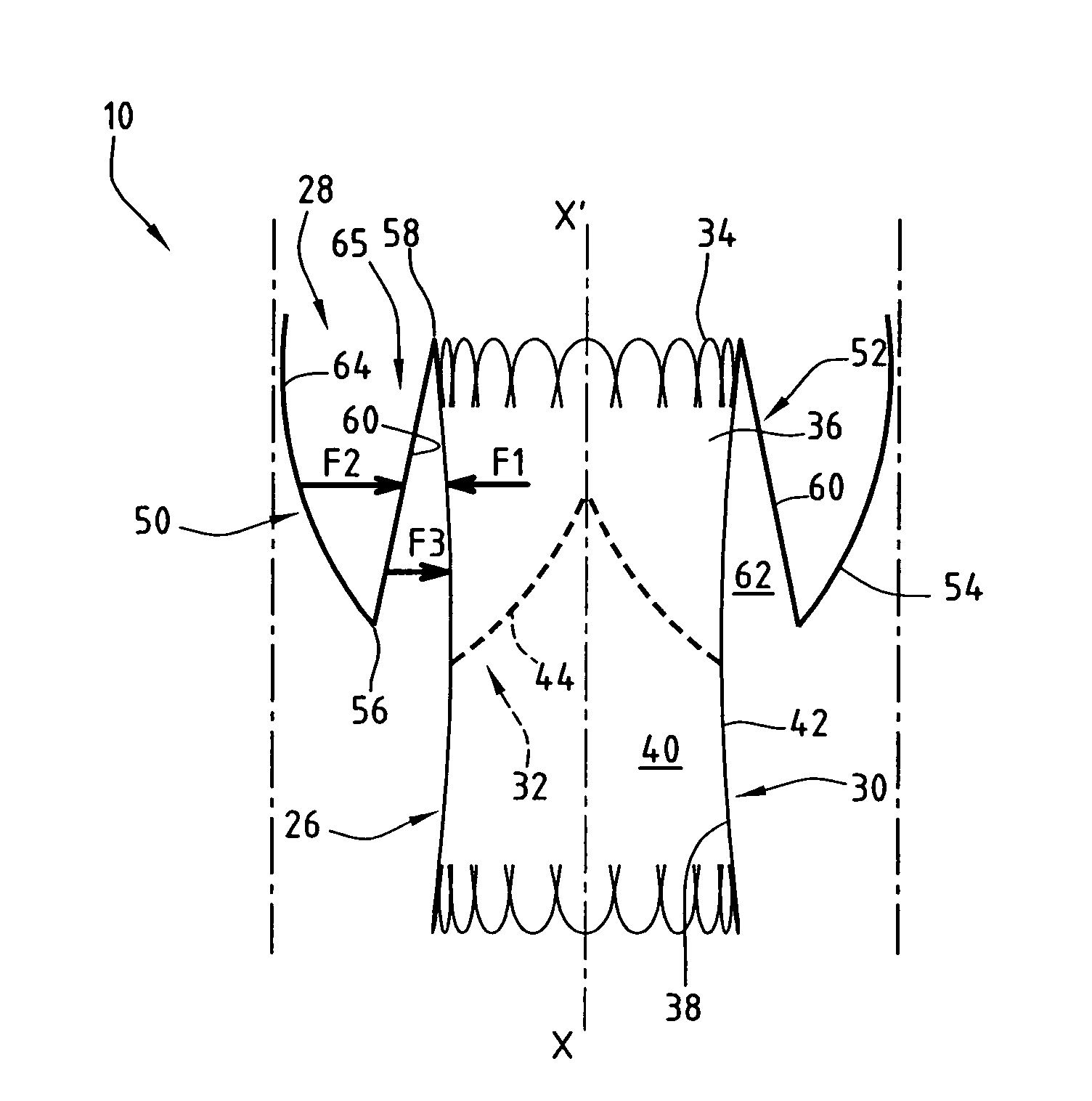
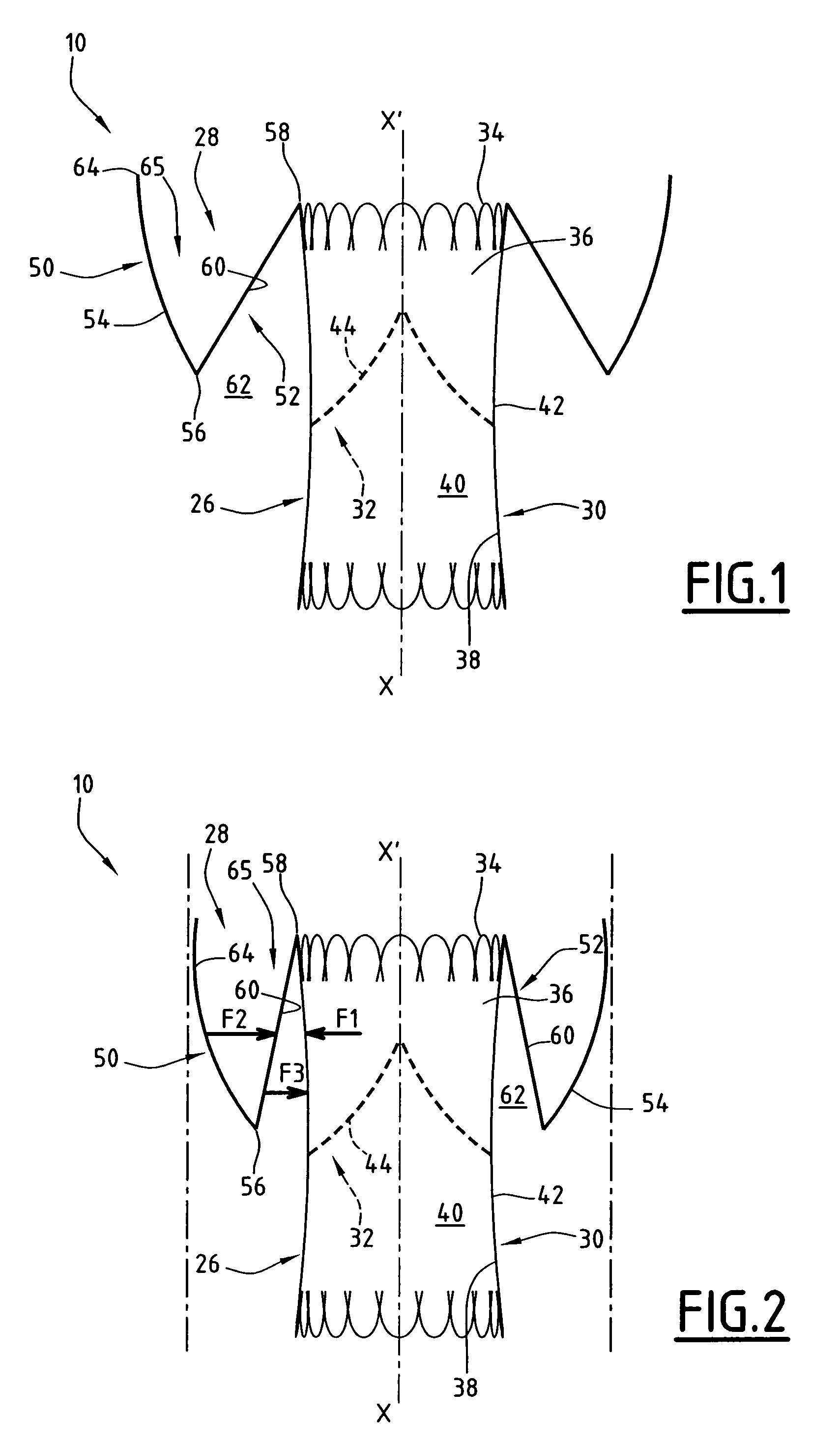
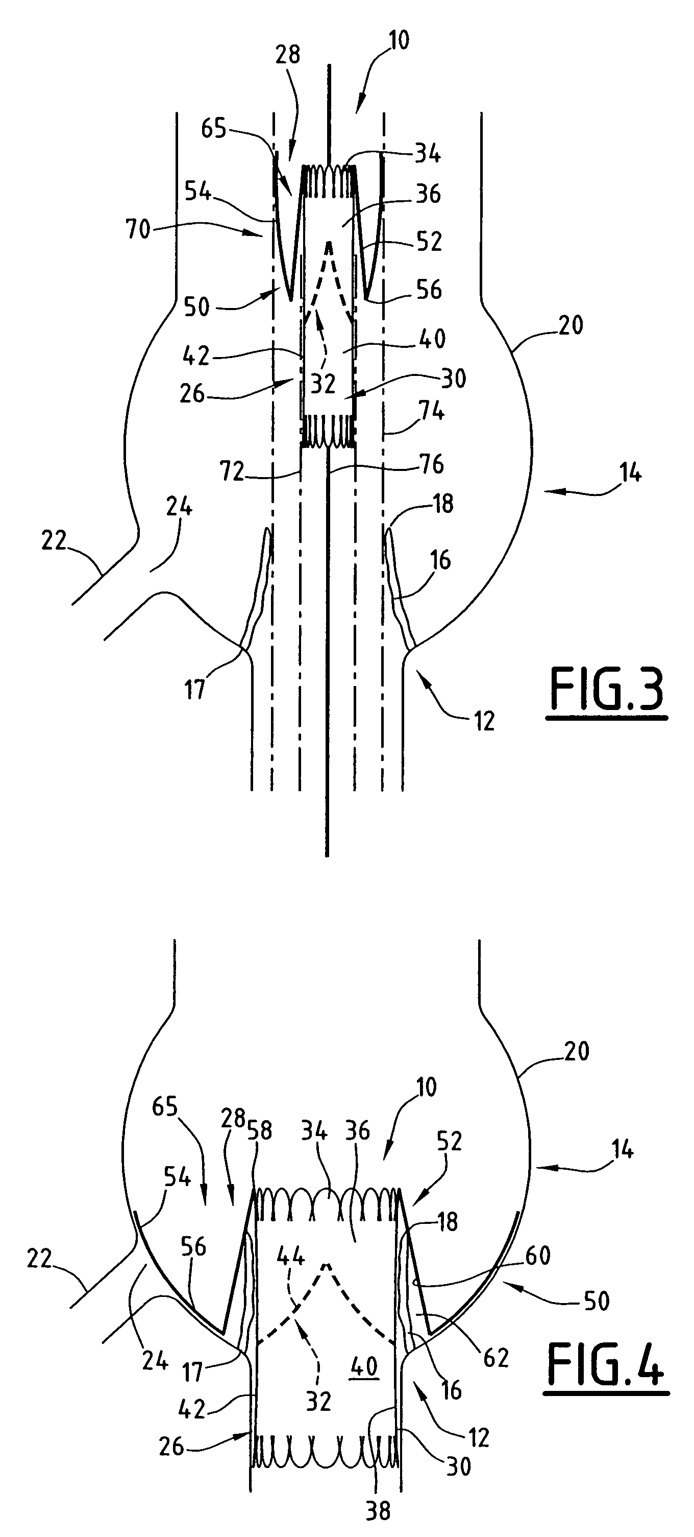
[0045]A first implant 10 according to the invention is illustrated in FIGS. 1 to 4. This implant 10 is intended to replace a defective natural valve 12 which can be seen in FIG. 3, in the coronary sinus 14.

[0046]The natural valve 12 comprises leaflets 16 which have a lower edge 17 which is articulated in the lower portion of the coronary sinus 12 and a free upper edge 18.

[0047]The coronary sinus 14 is delimited by a flared wall 20. Two coronary arteries 22, one of which can be seen in FIG. 3, open in the wall 20 through an opening 24.

[0048]In this example, the opening 24 is located opposite the leaflets 16 when these are pressed against the wall 20. It is therefore capable of being blocked by the leaflets 16.

[0049]As illustrated by FIGS. 1 and 2, the implant 10 comprises an endovalve 26 having a longitudinal axis X-X′, and the runners 28 which are permanently mounted on the endovalve protruding radially away from the axis X-X′ of the endovalve 26.

[0050]The endovalve 26 comprises a t...


PUM


Abstract

This implant comprises an endoprosthesis having an axis which can be spontaneously deployed in a radial manner between a compressed configuration and a dilated configuration. The implant comprises at least one radial runner which comprises a separation surface which extends radially with respect to an outer surface of the endoprosthesis and a member which can be deployed away from the axis. The runner is arranged so as to delimit a confinement housing which extends between the separation surface and the outer surface and a radial spacer which is defined by the separation surface and the deployable member. When the implant is retained in a state of radial compression, the maximum radial width of the housing is less than the maximum radial width of the spacer which is not equal to zero.

Description

BACKGROUND OF THE INVENTION[0001]I. Technical Field[0002]The present invention relates to an implant which is intended to be placed in a blood vessel, of the type comprising:[0003]an endoprosthesis which has a longitudinal axis and which can be deployed spontaneously in a radial manner from a compressed configuration to a dilated configuration, the endoprosthesis delimiting an inner passage for blood flow and an outer peripheral surface;[0004]at least one runner for radial support which co-operates with the endoprosthesis, the runner comprising a separation surface which extends radially with respect to the outer surface and at least one member which can be deployed away from the longitudinal axis relative to the separation surface.[0005]The invention is used in particular for the replacement of a natural cardiac valve with an endovalve.[0006]II. Description of the Prior Art[0007]The heart comprises valves which are present at the outlet of the right ventricle (pulmonary valve) and ...

Claims


Application Information

Patent Timeline
Patent Type & Authority Patents(United States)
IPC IPC(8): A61F2/24A61F2/848
CPCA61F2/2418A61F2002/8486A61F2250/006
Inventor STYRC, MIKOLAJPEROUSE, ERIC
Owner WL GORE & ASSOC INC
Why Eureka
Try Eureka