
Manually operable position sensor

a position sensor and operable technology, applied in the direction of resistors, non-adjustable resistors, garments, etc., can solve the problems of relatively high cost of tape itself and the cost of creating the assembly itsel

Inactive Publication Date: 2012-05-01
WEARABLE TECH LTD
View PDF13 Cites 5 Cited by
  • Summary
  • Abstract
  • Description
  • Claims
  • Application Information

AI Technical Summary

Benefits of technology

The fabric-based sensor provides a cost-effective and efficient means of transmitting control signals to electronic devices, enabling reliable position detection with reduced material costs and simplified assembly, while maintaining robust operation and accurate pressure sensing.

Problems solved by technology

The tape itself is relatively expensive and, furthermore, costs are involved in terms of creating the assembly itself.

Method used


Image

  • Manually operable position sensor
  • Manually operable position sensor
  • Manually operable position sensor

Examples


Embodiment Construction

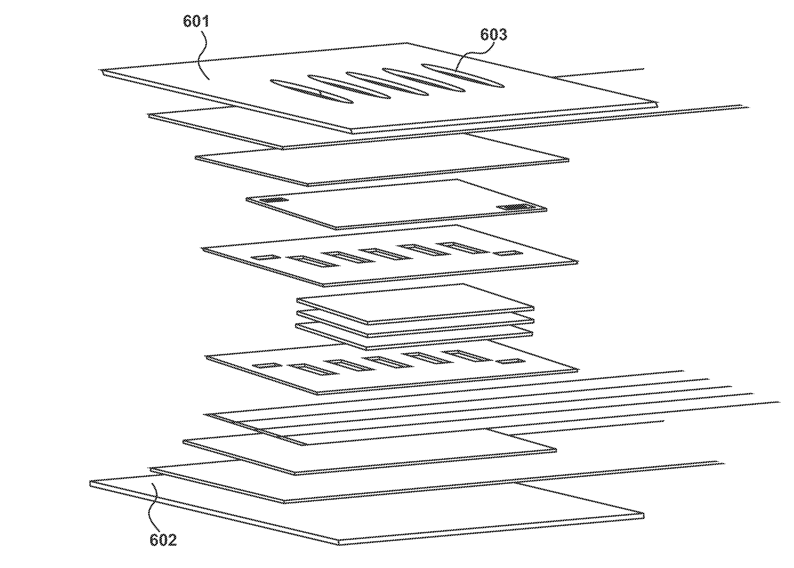
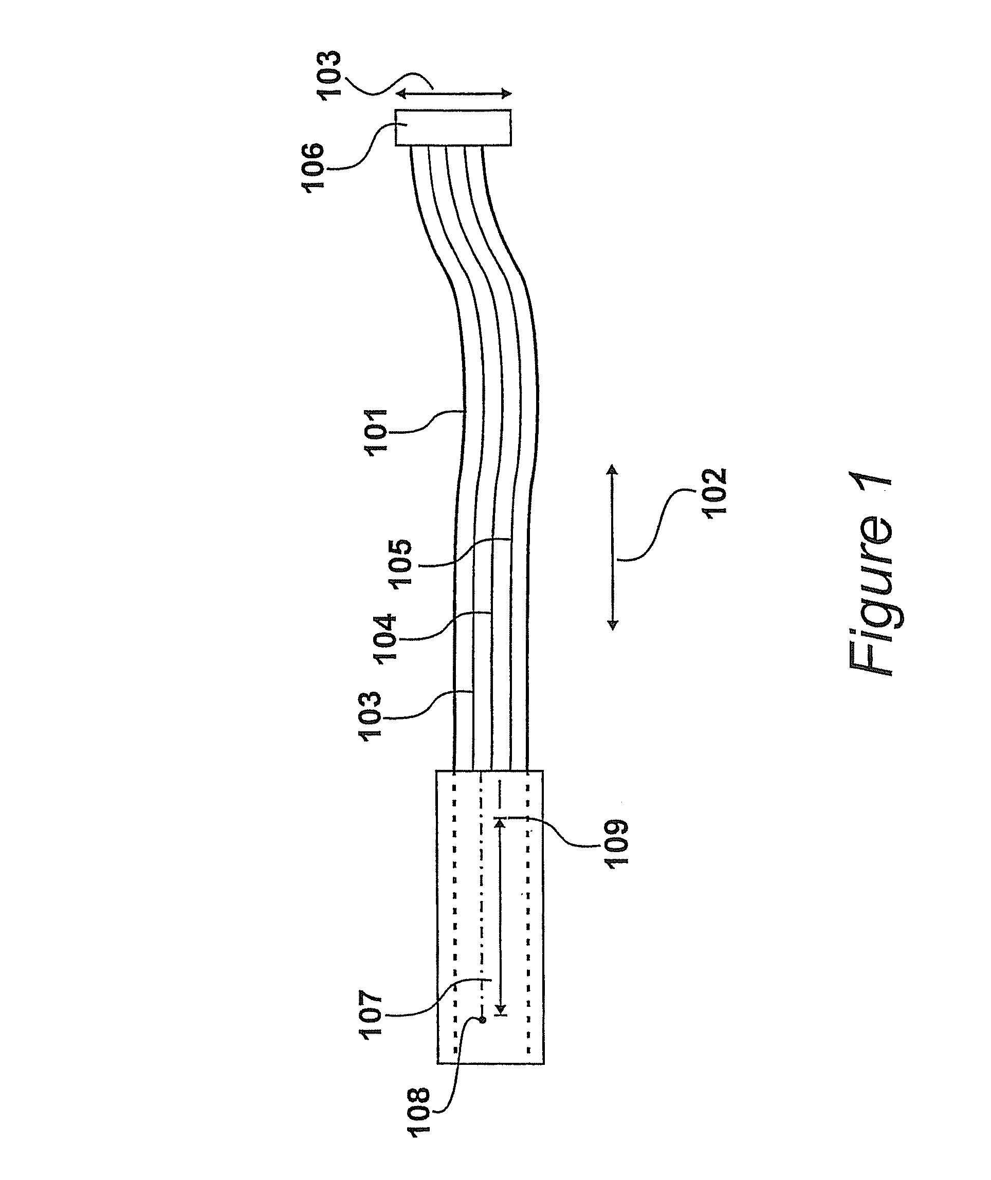
[0011]An embodiment of a manually operable position sensor is illustrated in FIG. 1. A fabric strip or ribbon 101 has a length, illustrated by arrows 102, that is substantially longer than its width, illustrated by arrow 103. For example, the length of ribbon 101 may be typically seven hundred and fifty millimetres with a typical width of twenty-five millimetres. The fabric has electrically insulating yarns and electrically conducting yarns included therein. The conducting yarns define three conductive tracks 103, 104 and 105 that are connected to an electrical connector 106. The electrical connector is provided to facilitate the interfacing of the sensor with an electronic device. At its opposite end, an active region 107 of the fabric forms part of a sensor assembly that is receptive to a manually applied pressure.

[0012]In a preferred sensor, the fabric is produced by a weaving process in which weft yarns are woven between warp yarns and the conducting yarns, that form tracks 103,...


PUM

PropertyMeasurementUnit
widthaaaaaaaaaa
widthaaaaaaaaaa
lengthaaaaaaaaaa

Abstract

A manually operable position sensor is shown, for providing control signals to an electronic device, such as an audio player. A fabric ribbon (101) has a length substantially longer than its width with insulating yarns and electrically conducting yarns included therein. The conducting yarns define three conductive tracks (103, 104, 105) running the length of the fabric. The conductive tracks are configured to interface with an electronic device at a first end. At a second end, an active region of the fabric forms part of a sensor assembly that is receptive to a manually applied pressure.

Description

CROSS REFERENCE TO RELATED APPLICATIONS[0001]This application claims priority from United Kingdom patent application number 0608329.9 filed 27 Apr. 2006, the entire contents of which are incorporated herein by reference.TECHNICAL FIELD[0002]The present invention relates to a manually operable position sensor for providing control signals to an electronic device.BACKGROUND OF THE INVENTION[0003]A manually operable position sensor is disclosed in U.S. Pat. No. 6,452,479, assigned to the present applicant. It is known for sensors of this type to communicate with electronic devices. In order to provide electrical communication between a sensor assembly and the electronic device, it is necessary to define tracks for electrical conduction. In known assemblies, these tracks are provided using electrically conductive tape surrounded by an insulating material. The tape itself is relatively expensive and, furthermore, costs are involved in terms of creating the assembly itself.BRIEF SUMMARY O...

Claims


Application Information

Patent Timeline
Patent Type & Authority Patents(United States)
IPC IPC(8): H01C10/10
CPCG06F1/163A41D1/002Y10T29/49117G06K11/06H01H13/70H01H13/702
Inventor WALKINGTON, STUART MARK
Owner WEARABLE TECH LTD
Learn More