Roll rigidity controller of vehicle

a technology of vehicle and control apparatus, which is applied in the direction of cycle equipment, instruments, transportation and packaging, etc., can solve the problem that the control apparatus cannot be optimally used, and achieve the effect of increasing and decreasing the anti-roll moment, increasing and decreasing the roll rigidity, and increasing and decreasing the support rigidity of the suspension

Inactive Publication Date: 2012-05-01
TOYOTA JIDOSHA KK
View PDF31 Cites 22 Cited by
  • Summary
  • Abstract
  • Description
  • Claims
  • Application Information

AI Technical Summary

Benefits of technology

[0014]Accordingly, as compared with the conventional roll rigidity control apparatus in which the target-roll control variable of the entire vehicle computed on the basis of lateral acceleration of the vehicle is distributed to the front and rear wheels so as to compute target-roll control variables for the front wheel position and the rear wheel position, and the roll rigidity changing means at the front wheel position and the rear wheel position are controlled on the basis of the target-roll control variables for the front wheel position and the rear wheel position, the roll rigidity at the front wheel position or the rear wheel position can be controlled reliably and accurately in accordance with the roll moment at the front wheel position or the rear wheel position, whereby optimal roll rigidity control can be performed reliably in accordance with the state of turn motion of the vehicle.
[0051]In the above-described configuration, the roll rigidity changing means may be configured to increase and decrease the support rigidity of a suspension, by increasing and decreasing the spring constant of a suspension spring, to thereby increase and decrease the roll rigidity.

Problems solved by technology

Therefore, the above-described conventionally known general roll rigidity control apparatus and the above-described previously proposed roll rigidity control apparatus cannot control the roll rigidities at the front wheel position and the rear wheel position while sufficiently taking into consideration that lateral acceleration differs between the front wheel position and the rear wheel position and that the difference in lateral acceleration changes depending on the state of turn motion of the vehicle.
Accordingly, the conventionally known roll rigidity control apparatus and the proposed roll rigidity control apparatus have a problem in that they cannot necessary perform optimal roll rigidity control in accordance with the state of turn motion of the vehicle.

Method used


Image

  • Roll rigidity controller of vehicle
  • Roll rigidity controller of vehicle
  • Roll rigidity controller of vehicle

Examples


first embodiment

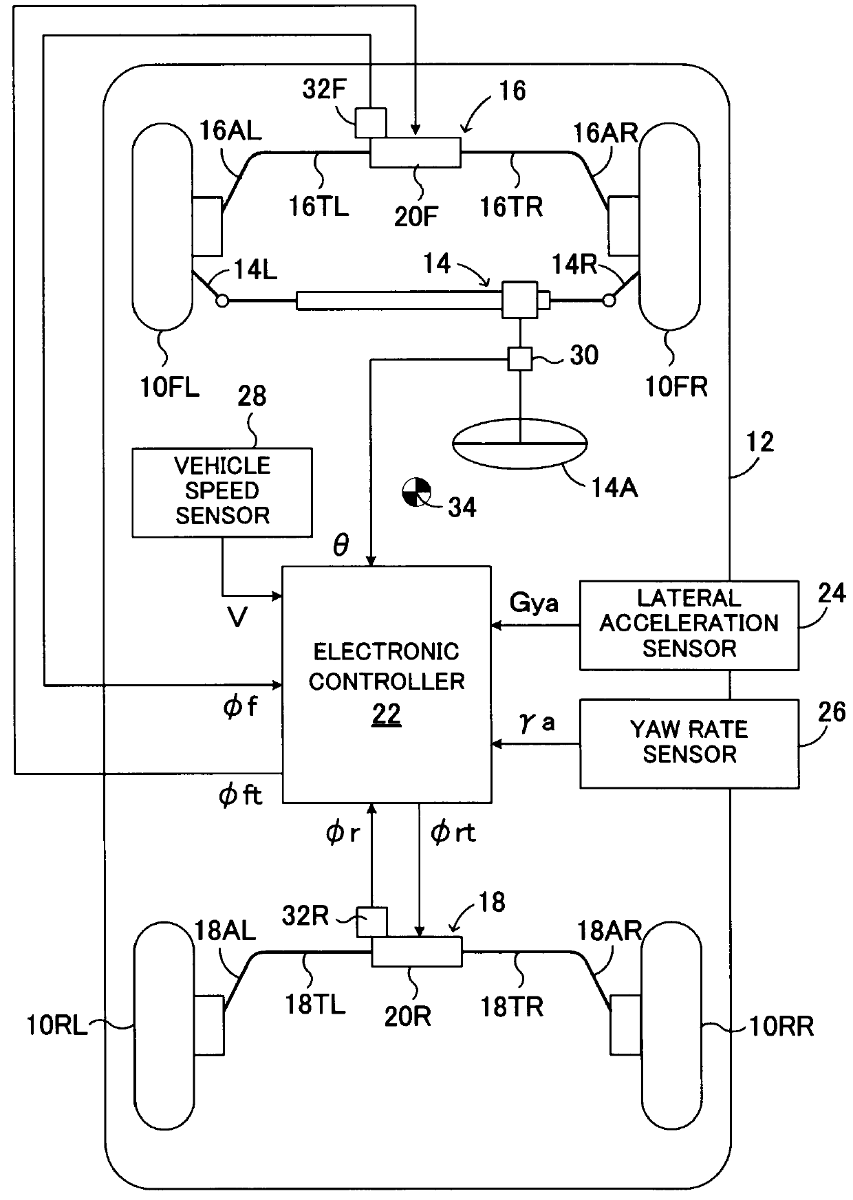
[0063]FIG. 1 is a schematic diagram showing a first embodiment of a vehicular roll rigidity control apparatus according to the present invention applied to a vehicle which includes active stabilizer apparatuses provided on the front wheel side and the rear wheel side.

[0064]In FIG. 1, reference numerals 10FL and 10FR respectively denote left and right front wheels of a vehicle 12, and 10RL and 10RR respectively denote left and right rear wheels of the vehicle 12. The left and right front wheels 10FL and 10FR, which are steerable wheels, are steered via tie rods 14L and 14R by means of a power steering apparatus 14, which is driven in response to steering operation of a steering wheel 14A by a driver. Notably, the vehicle to which the roll rigidity control apparatus of the present invention is applied may be of a front-wheel drive type, a rear-wheel drive type, or a four-wheel drive type.

[0065]An active stabilizer apparatus 16 is provided between the left and right front wheels 10FL a...

second embodiment

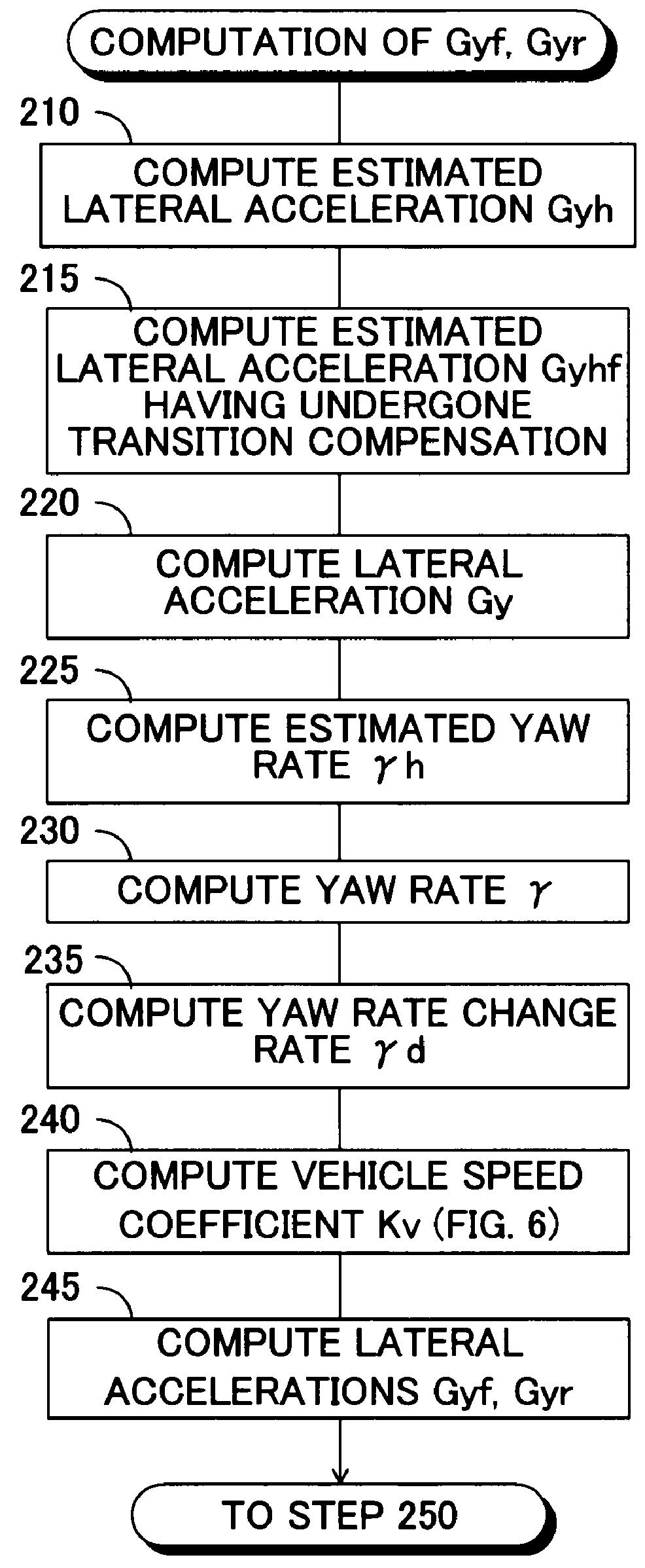
[0096]FIG. 7 is a flowchart showing a lateral acceleration computation routine in a second embodiment of the vehicular roll rigidity control apparatus according to the present invention. Notably, in FIG. 7, steps identical with those shown in FIG. 3 are denoted by the same step numbers as those used in FIG. 3.

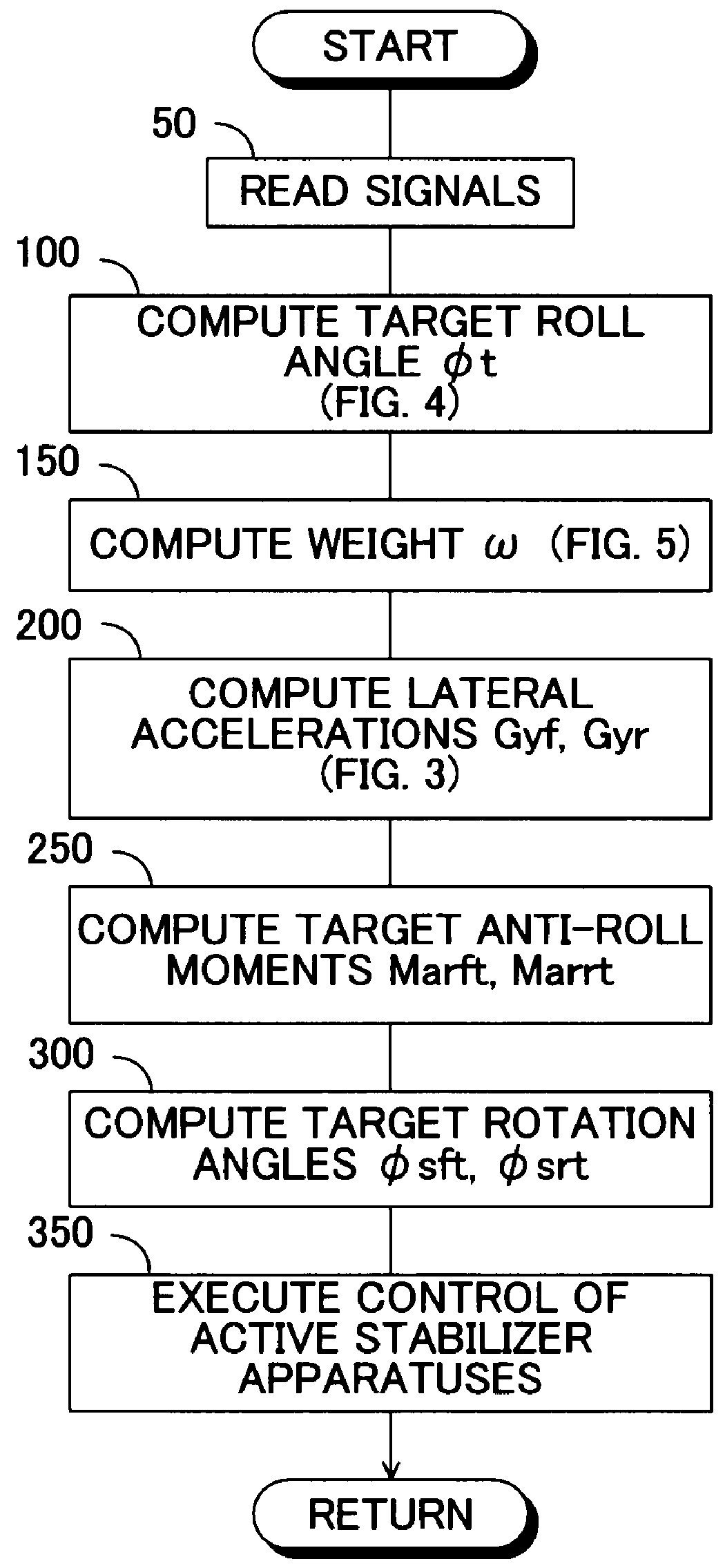
[0097]In this second embodiment, the main routine for roll rigidity control is performed in the same manner as in the above-described first embodiment in accordance with the flowchart shown in FIG. 2, except that the lateral accelerations Gyf and Gyr of the vehicle at the front wheel position and the rear wheel position are computed in step 200 in accordance with the flowchart shown in FIG. 7. Further, as shown in FIG. 7, steps 210 to 220, 240, and 245 of the lateral acceleration computation routine are executed in the same manner as in the above-described first embodiment.

[0098]After completion of step 220, without performance of steps corresponding to steps 225 and 230 in the...


PUM


Abstract

A target roll angle of the vehicle is computed based on an actual lateral acceleration at the centroid of the vehicle, and the lateral acceleration of the vehicle at the centroid is corrected by use of lateral acceleration correction amounts based on a yaw rate of the vehicle, whereby the lateral accelerations of the vehicle at the front wheel position and the rear wheel position are computed. Subsequently, target anti-roll moments at the front wheel position and the rear wheel position are computed based on the target roll angle and the accelerations of the vehicle at the front wheel position and the rear wheel position, and active stabilizer apparatuses of the front and rear wheels are controlled based on these target anti-roll moments.

Description

TECHNICAL FIELD[0001]The present invention relates to a roll rigidity control apparatus for a vehicle, and more particularly to a roll rigidity control apparatus for a vehicle which includes roll rigidity changing means at a front wheel position or a rear wheel position.BACKGROUND ART[0002]In general, a roll rigidity control apparatus for a vehicle, such as an automobile, which apparatus includes roll rigidity changing means, such as an active stabilizer apparatus, at a front wheel position and a rear wheel position, is configured to compute a target-roll control variable of the entire vehicle from lateral acceleration of the vehicle, distribute the target-roll control variable of the entire vehicle to front and rear wheels on the basis of a front-rear distribution ratio of roll rigidity to thereby compute target-roll control variables for the front wheel position and the rear wheel position, and control the roll rigidity changing means at the front wheel position and the rear wheel...

Claims


Application Information

Patent Timeline
Patent Type & Authority Patents(United States)
IPC IPC(8): B60G17/016B60G21/055
CPCB60G21/0558B60G2400/0521B60G2400/0523B60G2400/104
Inventor MIZUTA, YUICHI
Owner TOYOTA JIDOSHA KK
Why Eureka
Try Eureka