Extruder

a technology of extruder and kneading head, which is applied in the direction of mixing/kneading with horizontally mounted tools, mechanical equipment, couplings, etc., to achieve the effect of increasing the volume yield

Inactive Publication Date: 2012-05-08
BLACH VERWALTUNGS GMBH
View PDF14 Cites 6 Cited by
  • Summary
  • Abstract
  • Description
  • Claims
  • Application Information

AI Technical Summary

Benefits of technology

[0011]According to the invention, the flight depth of the conveying or similar slip-on element is increased at high torque transmission of the shaft-to-hub connection. That is, at equal center distance the outside diameter of the slip-on element is greater and the core diameter of the slip-on element reduced by the same measure, which considerably increases the free conveying surface of the conveying element or working surface of the working element and thus the performance of the extruder.
[0015]This is obtained in the invention by providing no force transmission of the shaft-to-hub connection in this area. Thus, the cross-sectional area that the shaft-to-hub connection otherwise occupies in this area can be added to the cross-sectional area of the slip-on element in this area and thus the flight depth accordingly increased without impairing the strength of the support shaft.
[0017]A support shaft configured according to the invention can be produced in a simple manner by removing the toothing of the shaft, e.g. by grinding, from a conventional support shaft, e.g. an involute shaft as according to DIN 5480, in the area against which the slip-on element lies with its thinnest area corresponding to the circular arc of the slip-on element core diameter.
[0021]As calculations and experiments have shown, the inventive extruder can increase volume yield by about 30% at equal torque.
[0022]Moreover, the invention increases the sealing surface preventing material from penetrating between the slip-on elements and the shaft and cracking there.

Problems solved by technology

Secondly, the support shaft requires the calculated usable surface proportion for axially conducting the required shaft torque for the subsequent slip-on elements.

Method used


Image

  • Extruder
  • Extruder
  • Extruder

Examples


Embodiment Construction

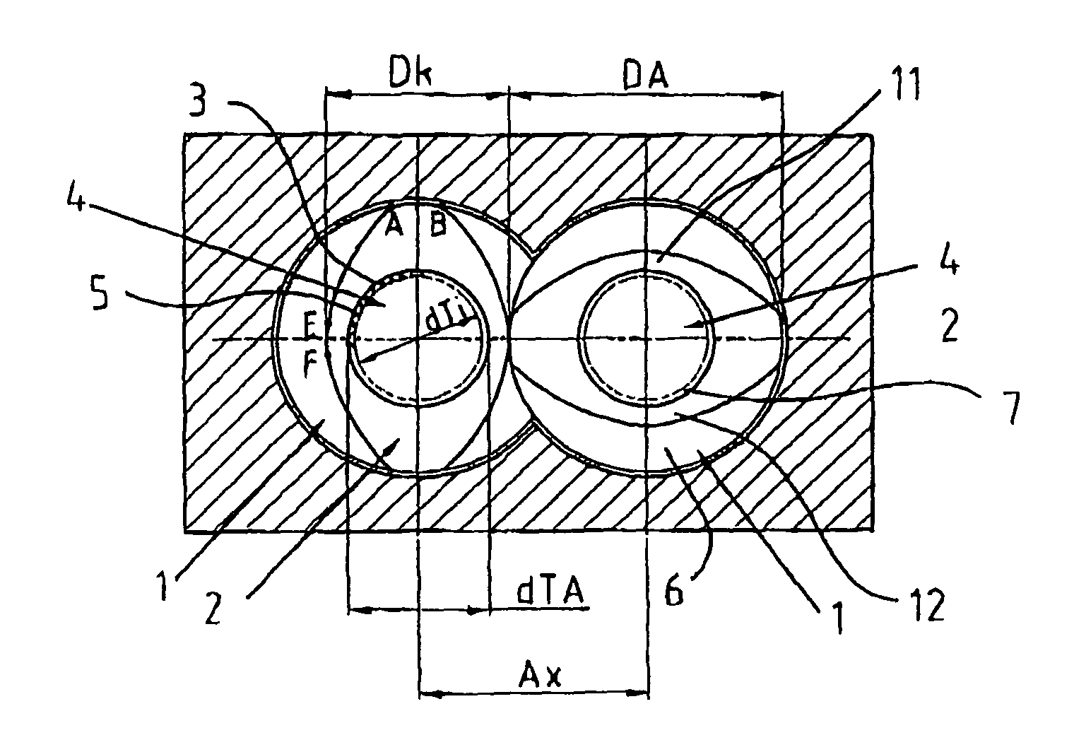
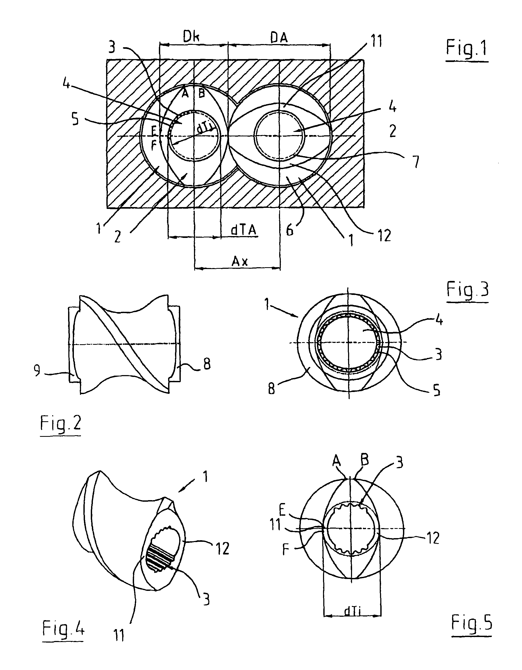
[0031]As shown in FIG. 1, two intermeshing slip-on elements 1 have a transverse or cross-sectional profile area 2 which is limited by circular arcs A-B, E-F and A-E. The circular arc A-B has a diameter corresponding to the maximum slip-on element diameter DA, the circular arc E-F a diameter corresponding to the slip-on element core diameter Dk, and the circular arc A-E a diameter whose radius corresponds at most to the center distance Ax of the two combined slip-on elements 1.

[0032]The slip-on element 1 has an internal toothing 3 engaged by the support shaft 4 with its external toothing 5. The slip-on element thus has a free conveying surface 6 that is determined by the diameter DA and the flight depth. Further, the surface proportion 7 for the shaft-to-hub connection is needed, which results from dTA and dTi.

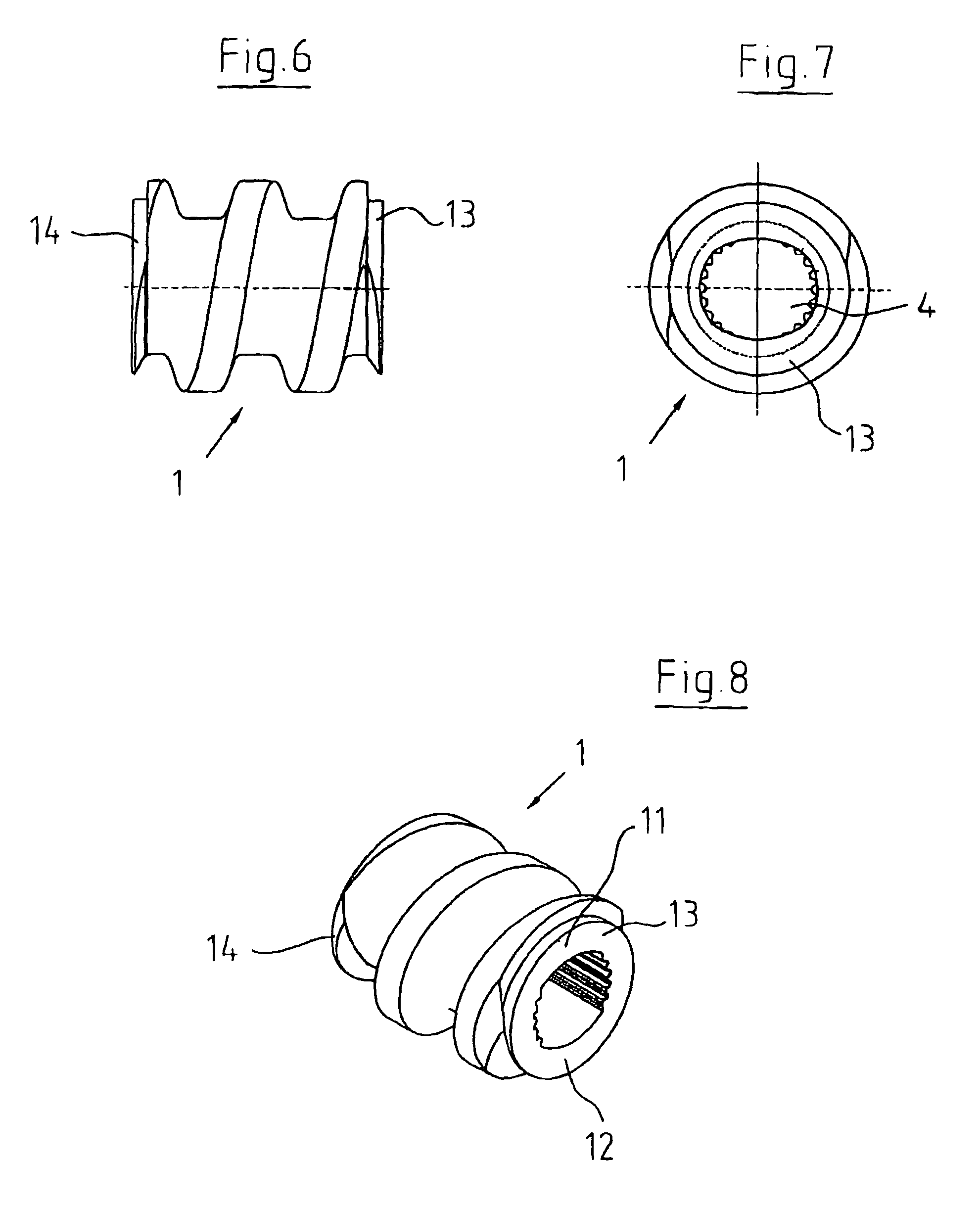
[0033]According to FIGS. 2 and 3, the slip-on element 1 configured as a screw element likewise has an internal toothing 3 engaged by the support shaft 4 all around with its ext...


PUM

PropertyMeasurementUnit
diameteraaaaaaaaaa
DAaaaaaaaaaa
areasaaaaaaaaaa

Abstract

In an extruder wherein the slip-on elements (1) have a cross-sectional profile comprising circular arcs corresponding to the maximum slip-on element diameter, the slip-on element core diameter and the center distance of the slip-on elements (1), the slip-on element (1) has no shaft-to-hub connection in the area of the circular arc corresponding to the slip-on element core diameter and / or it is provided at its ends with reinforcement segments (13, 14).

Description

FIELD OF THE INVENTION[0001]This invention relates to an extruder having at least two support shafts having slip-on elements configured as conveying and / or working elements.BACKGROUND OF THE INVENTION[0002]For nonrotatably connecting the support shaft with the screws or similar slip-on elements, different shaft-to-hub connections are known.[0003]Thus, DE-C 813 154 discloses a machine with two shafts wherein a feather key or a square profile is used as a shaft-to-hub connection. According to DE 77 01 692 U1 a multiple spline shaft is used as a shaft-to-hub connection with an integrated spline, while DE 27 50 767 A1 and EP 0 001 970 A1 describe circular shafts with three separate sunk keys with the same pitch angle, and EP 0 330 308 A1 two keys with an unequal pitch angle. What is primarily used nowadays, however, is the involute shaft according to DIN 5480.[0004]Further, there are described and compared in “Konstruktionsbücher,” Springer-Verlag, 1984, pages 210 and 211, a variety of ...

Claims


Application Information

Patent Timeline
Patent Type & Authority Patents(United States)
IPC IPC(8): B01F7/08B29C48/40
CPCB29C47/0825B29C47/40B29C47/60F16D1/101B29C47/0009B29C48/03B29C48/2564B29C48/40F16D2001/103F16D1/06
Inventor BLACH, JOSEF A.
Owner BLACH VERWALTUNGS GMBH
Why Eureka
Try Eureka