Method for mating flexure to flex-print circuit and flexure therefor

a technology of flexure and flexure parts, which is applied in the direction of maintaining head carrier alignment, manufacturing tools, instruments, etc., can solve the problems of inability to inspect the integrity of bonding and/or repair, inability to make any repairs, and inability to inspect the integrity of bonding and/or bonding, etc., to facilitate visual inspection of mated fpc/flexure parts, facilitate visual inspection and rework of solder

Active Publication Date: 2012-05-08
NITTO DENKO CORP
View PDF13 Cites 8 Cited by
  • Summary
  • Abstract
  • Description
  • Claims
  • Application Information

AI Technical Summary

Benefits of technology

[0013]Various embodiments of the subject invention facilitate visual inspection of mated FPC / flexure parts and enable rework of solder bridging between adjacent conductors should they occur. The various embodiments of the invention are applicable to both CIS, ILS and TSA flexure circuits. According to various embodiments of the invention, small windows (or openings) are cut or formed into the base polyimide between adjacent conductors to facilitate visual inspection and rework of solder. This will allow visual inspection and also allow the rework of pieces that would otherwise be scrapped.

Problems solved by technology

Poor alignment may result in shorts (solder bridging) between adjacent conductors or opens.
Additionally, once the two parts are bonded or soldered, there is no possibility to inspect the integrity of the bonding and / or to make any repairs.
As can be seen from these Figures, the proper alignment of the CIS and FPC cannot be verified, and errors cannot be corrected.

Method used


Image

  • Method for mating flexure to flex-print circuit and flexure therefor
  • Method for mating flexure to flex-print circuit and flexure therefor
  • Method for mating flexure to flex-print circuit and flexure therefor

Examples


Embodiment Construction

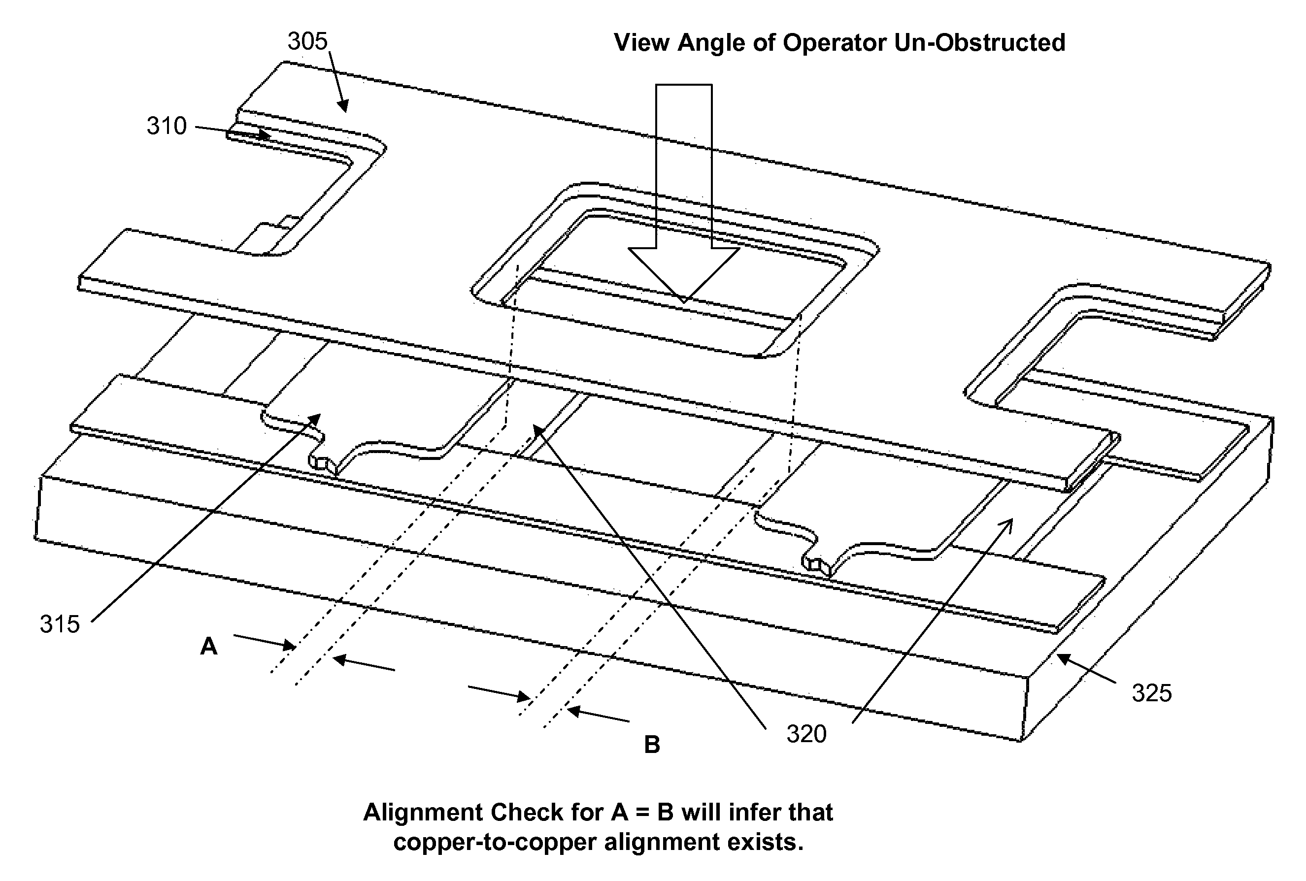
[0031]FIG. 3a is a top view of a CIS over FPC in proper alignment according to an embodiment of the invention, while FIG. 3b is a semi-exploded view of the CIS and FPC according to an embodiment of the invention. As shown, the CIS flexure of this embodiment comprises a sandwich of steel upper layer 305 (e.g., stainless steel), an insulating substrate 310, e.g., polyimide layer, and a plurality of conducting contacts 315, e.g., copper traces. The contacts 315 need to be aligned with and connected to the FPC contacts 320, which are generally also copper traces. The FPC contacts 320 are provided over the FPC substrate 325. These described elements are similar to the elements of the prior art FPC and flexure. However, unlike the prior art, as shown in FIGS. 3a and 3b, windows or cut-outs 350 are made in the CIS substrate 310 corresponding to and aligned with windows or cut-outs in the CIS steel layer 305. This enables visual inspection of the alignment of the flexure contacts 315 and FP...


PUM

PropertyMeasurementUnit
conductiveaaaaaaaaaa
widthaaaaaaaaaa
flexibleaaaaaaaaaa

Abstract

Inspection windows are cut or formed into the tail section of the flexure circuit tail in a hard disk drive Head Gimbal Assembly (HGA), or CIS, to enable visual inspection of the alignment of the CIS to the head preamp circuit, or FPC. The holes are made in the steel backing and base polyimide, and are positioned between adjacent conductive pads. In addition to facilitating visual inspection, the windows also enable rework of solder. Additionally, solder wicking holes may also be provided in the conductive pads and / or the polyimide and steel backing.

Description

RELATED APPLICATIONS[0001]This application claims priority from U.S. Provisional Application Ser. No. 60 / 854,486, filed Oct. 25, 2006, the disclosure of which is incorporated herein by reference in its entirety.BACKGROUND[0002]1. Field of the Invention[0003]This invention relates to manufacturing of hard disk drives (HDD) and, more particularly, to assembly, manufacturing and inspection of hard disk drive components.[0004]2. Description of Related Art[0005]FIGS. 1a and 1b depict a hard drive suitable for implementing embodiments of the subject invention. FIG. 1a depicts the hard drive 100 with the cover removed, while FIG. 1b depicts an enlarged image of the preamp area of the hard drive 100. The hard drive 100 uses rotating platters (disks) 110 to store data. Each platter is rotated by a spindle (not shown) and has a smooth magnetic coated surface on which digital data is stored. Information is written to the disk by applying a magnetic field from a read-write head (not shown) that...

Claims


Application Information

Patent Timeline
Patent Type & Authority Patents(United States)
IPC IPC(8): H05K1/11G11B5/48G11B21/16G11B5/60G11B15/64G11B17/32G11B21/20
CPCH05K3/363G11B5/4846H05K1/0269H05K1/056Y10T29/49124H05K2201/0969Y10T29/53209H05K2201/09063
Inventor CAYABAN, ALEX ENRIQUEZALEKSIC, VLADIMIRWAKAKI, SHUICHI
Owner NITTO DENKO CORP
Why Eureka
Try Eureka