
Reduction of memory size required for correction of displacement of scan positions

a technology of scan position and memory size, applied in image enhancement, visual presentation, instruments, etc., can solve the problem of increasing the size of the required memory

Inactive Publication Date: 2012-05-08
RICOH KK
View PDF13 Cites 4 Cited by
  • Summary
  • Abstract
  • Description
  • Claims
  • Application Information

AI Technical Summary

Benefits of technology

The present invention provides a displacement correcting scheme that overcomes the limitations and disadvantages of existing methods. The invention includes an apparatus for correcting a scanned image by aligning first and second image data corresponding to two of a plurality of sensor lines, when the sensor lines scan image data at a predetermined line interval in a sub-scan direction. The apparatus includes a delay circuit, an interpolation circuit, and a control circuit. The delay circuit delays the first image data by an amount corresponding to an integer multiple of the line interval. The interpolation circuit performs an interpolation computation with respect to interpolation coefficients with respect to two or more lines in the first image data. The control circuit sets the delay amount and the interpolation coefficients, ensuring that the delay is equal to an interval between the first and second image data if the interval is n times the line interval. The invention also includes a method for correcting displacement in a scanned image by aligning first and second image data corresponding to two of a plurality of sensor lines, when the sensor lines scan image data at a predetermined line interval in a sub-scan direction. The method includes delaying the first image data, performing an interpolation computation with respect to interpolation coefficients with respect to two or more lines, and setting the delay amount and the interpolation coefficients to ensure that the delay is equal to an interval between the first and second image data if the interval is n times the line interval. The technical effects of the invention include improved accuracy and efficiency in correcting displacement in scanned images.

Problems solved by technology

In such a case, there is a problem in that a displacement corresponding to a fraction of one line remains after delaying the R image data and G image data by an integer multiple of the 1-line scan interval as in the related art.
If the intervals of the RGB line sensors are wide, or if the scan resolution is high, there is a problem of the required memory size being increased.

Method used


Image

  • Reduction of memory size required for correction of displacement of scan positions
  • Reduction of memory size required for correction of displacement of scan positions
  • Reduction of memory size required for correction of displacement of scan positions

Examples


first embodiment

[0054]In the following, a description will be given of a first embodiment of an image forming apparatus provided with a scanned image correcting apparatus according to the present invention.

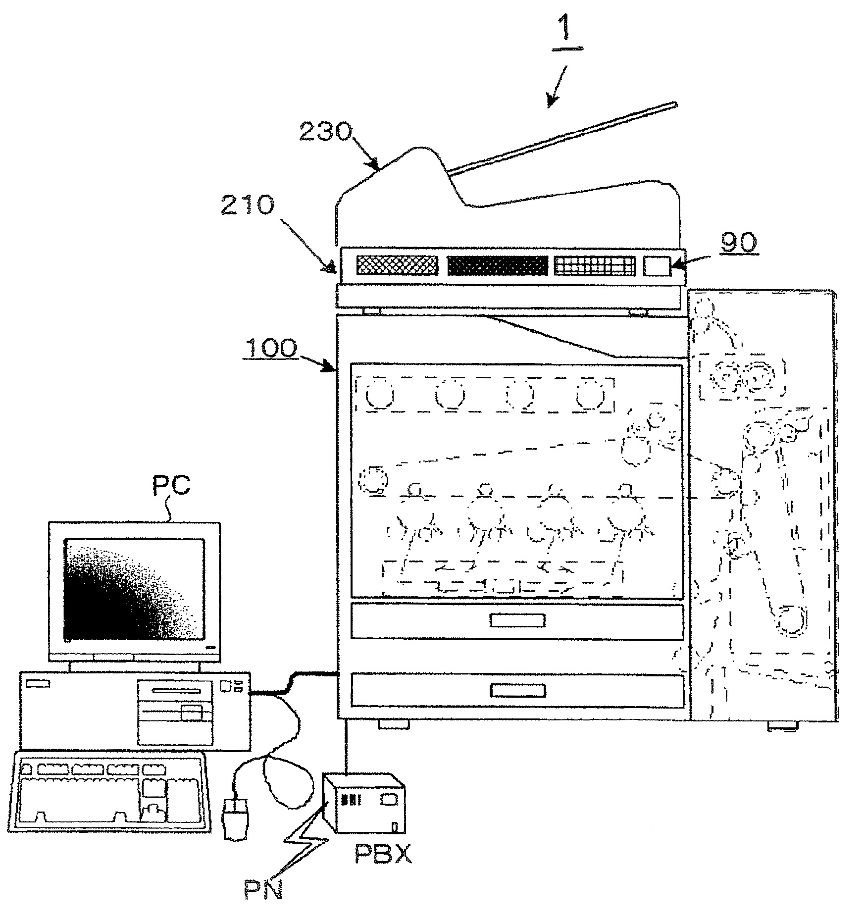
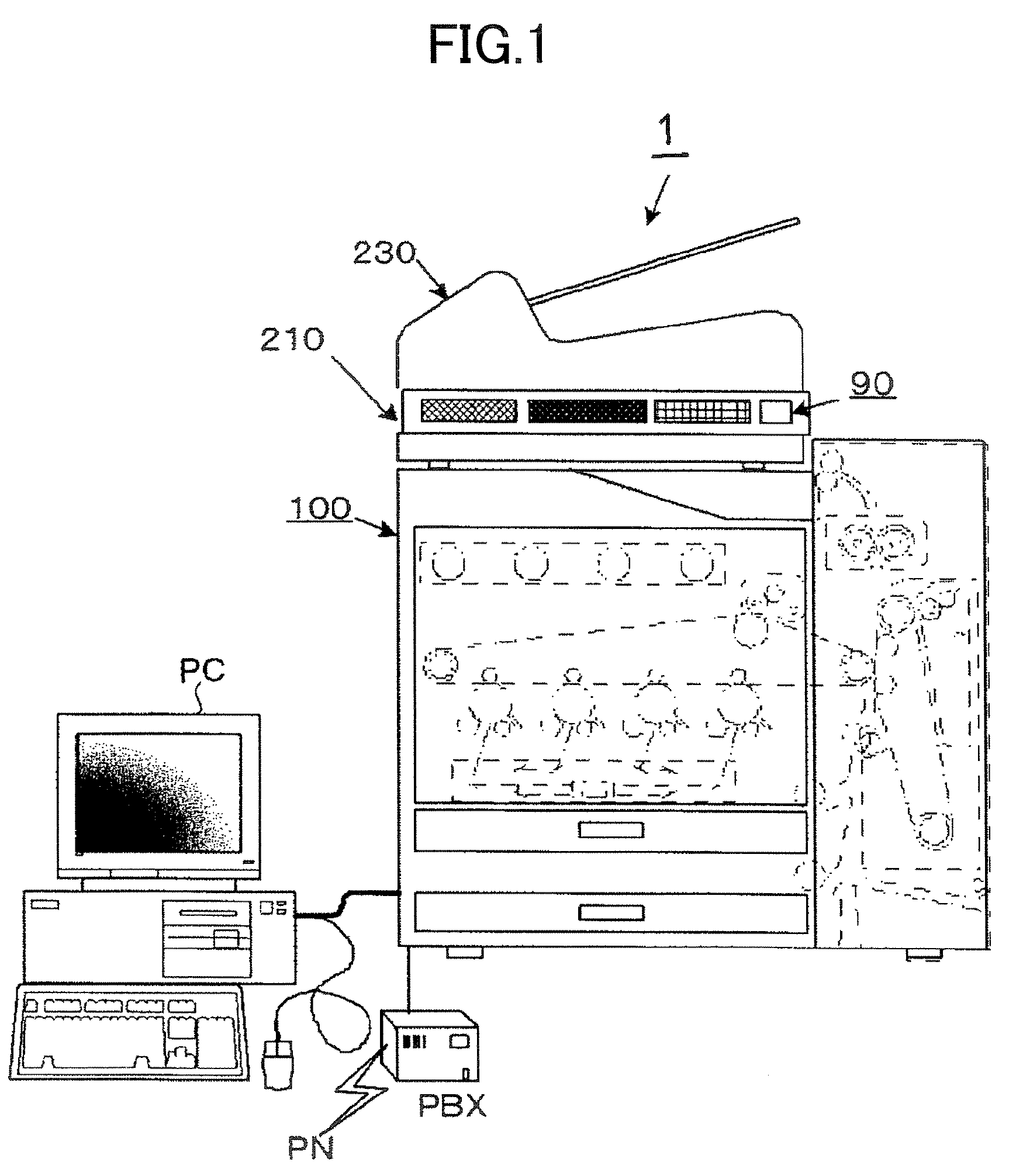
[0055]The image forming apparatus of the first embodiment is a multifunctional full-color digital copier (hereinafter simply referred to as a “digital copier”) that forms a color image by an electrophotographic process. FIG. 1 is a drawing showing an example of a schematic configuration of the copier system inclusive of the digital copier.

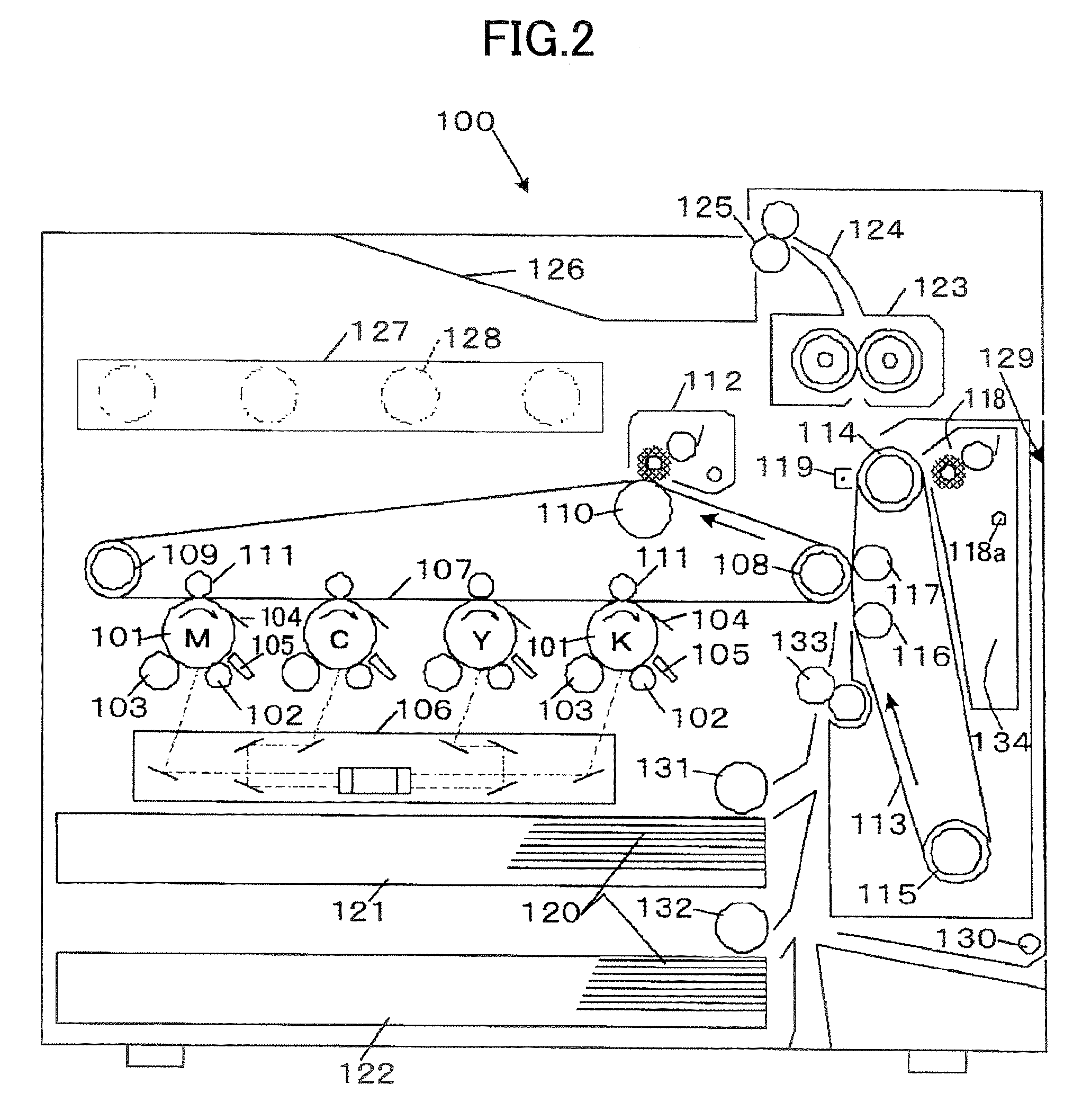
[0056]The digital copier 1 includes a plurality of units such as an auto document feeder 230, an operation board 90, a color scanner (image scan apparatus) 210, and a color printer 100. The color scanner 210 on which the operation board 90 and the auto document feeder 230 are mounted is a unit that is separable from the color printer 100. The color scanner 210 includes a control board having power-device drivers, sensor inputs, and a controller, and communicates...

second embodiment

[0188]In the following, a description will be given of a second embodiment of an image forming apparatus provided with a scanned image correcting apparatus according to the present invention. The second embodiment differs from the first embodiment only in the configuration of the scanner image processing unit 263, and a description will be given with focus on such difference.

[0189]FIG. 15 is a block diagram showing a second example of the configuration of the AFE 212 and the scanner image processing unit 263 shown in FIG. 4. In FIG. 15, the same elements as those of FIG. 7 are referred to by the same numerals.

[0190]In the second embodiment, the scanner image processing unit 263 shown in FIG. 15 includes a delay unit 22b for the image data B additionally provided on top of the configuration shown in FIG. 7 (first embodiment). The delay unit 22b will later be described.

[0191]Among the units shown in FIG. 15, the CCD 207, the analog signal processing units 11r, 11g, and 11b and A / D con...

third embodiment

[0230]In the following, a description will be given of a third embodiment of an image forming apparatus provided with a scanned image correcting apparatus according to the present invention. The third embodiment differs from the first and second embodiments only in the configuration of the scanner image processing unit 263, and a description will be given with focus on such difference.

[0231]FIG. 22 is a block diagram showing a third example of the configuration of the AFE 212 and the scanner image processing unit 263 shown in FIG. 4. In FIG. 22, the same elements as those of FIG. 15 are referred to by the same numerals.

[0232]In the third embodiment, the scanner image processing unit 263 shown in FIG. 22 includes an interpolation unit 23b for the image data B additionally provided on top of the configuration shown in FIG. 15 (second embodiment). This configuration is made in order to cope with the reversal of the displacements between line sensors between the case in which an image o...


PUM


Abstract

An apparatus for correcting a scanned image includes a delay circuit configured to delay first image data by a delay amount corresponding to an integer multiple of a line interval, an interpolation circuit configured to perform an interpolation computation responsive to interpolation coefficients with respect to two or more lines included in the first image data delayed by the delay circuit, and a control circuit configured to set the delay amount to the delay circuit and the interpolation coefficients to the interpolation circuit, wherein the control circuit is configured to set the delay amount to an amount corresponding to integer m smaller than integer n and set the interpolation coefficients such that the interpolation computation becomes equivalent to a computation introducing a delay equal to n−m lines if an interval between the first image data and second image data is n times the line interval.

Description

BACKGROUND OF THE INVENTION[0001]1. Field of the Invention[0002]The present invention relates to a scanned image correcting apparatus for correcting the displacements of scan positions in scanned image data (image signals) that are scanned by a plurality of line image sensors (scan means), an image scan apparatus such as a scanner equipped with such a scanned image correcting apparatus, and an image forming apparatus such as a copier machine, a multifunctional machine, or a facsimile machine that is equipped with such an image scan apparatus.[0003]2. Description of the Related Art[0004]In a conventional image scan apparatus such as a scanner, as shown in FIG. 6, a color image sensor (i.e., three-line color CCD) 207 is used to perform a scan where the color image sensor 207 includes individual line sensors 10r, 10g, and 10b corresponding to R, G, and B. The line sensors 10r, 10g, and 10b corresponding to R, G, and B are arranged in parallel at intervals each equal to a predetermined ...

Claims


Application Information

Patent Timeline
Patent Type & Authority Patents(United States)
IPC IPC(8): H04N1/04
CPCH04N1/486
Inventor INUKAI, YOSHIHIRO
Owner RICOH KK
Learn More