
System and method for transmitting optical signals

a transmission system and optical signal technology, applied in the field of optical signal transmission system, can solve the problems of not being able to simply extract the desired wavelength and route it to the terminal station without significant impact on wavelength performance, and achieve the effect of large bandwidth capacity

Active Publication Date: 2015-05-12
ALCATEL LUCENT SAS
View PDF37 Cites 0 Cited by
  • Summary
  • Abstract
  • Description
  • Claims
  • Application Information

AI Technical Summary

Benefits of technology

[0017]outputting the replicated optical spectrum from the coupler / splitter into an input port of an optical fiber having a predetermined length so as to introduce a delay in the optical path of the wavelengths,

Problems solved by technology

In such a case, there is no possible access by other customers that are allocated other fiber pairs, to the fiber pair of that particular customer.
In a submarine network comprising repeaters, and assuming that the repeaters are identical as regards their technical characteristics, when it is desired to branch-off one or more wavelengths from the main line (trunk) to the branch terminal station, it is not possible to simply extract the desired wavelengths and route them to the terminal station without a significant impact on the wavelength performance.
This is due to the fact that the repeaters designed to have large bandwidth capacities are not optimized in gain and in output power to transmit only few wavelengths.
This possibility may give rise to problems in optical networks in which the traffic data may be subjected to confidentiality considerations.
Therefore, this possibility of having access to other customers' wavelengths may become undesirable in view of confidentiality considerations in certain countries.

Method used


Image

  • System and method for transmitting optical signals
  • System and method for transmitting optical signals

Examples


Embodiment Construction

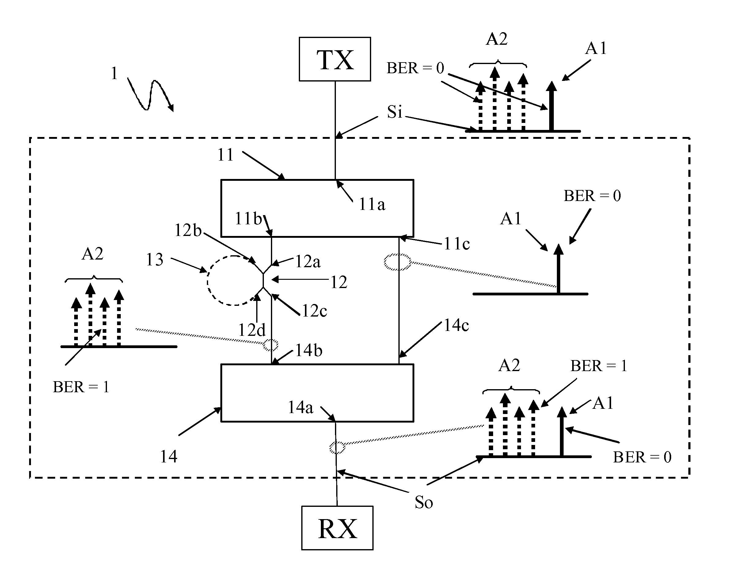
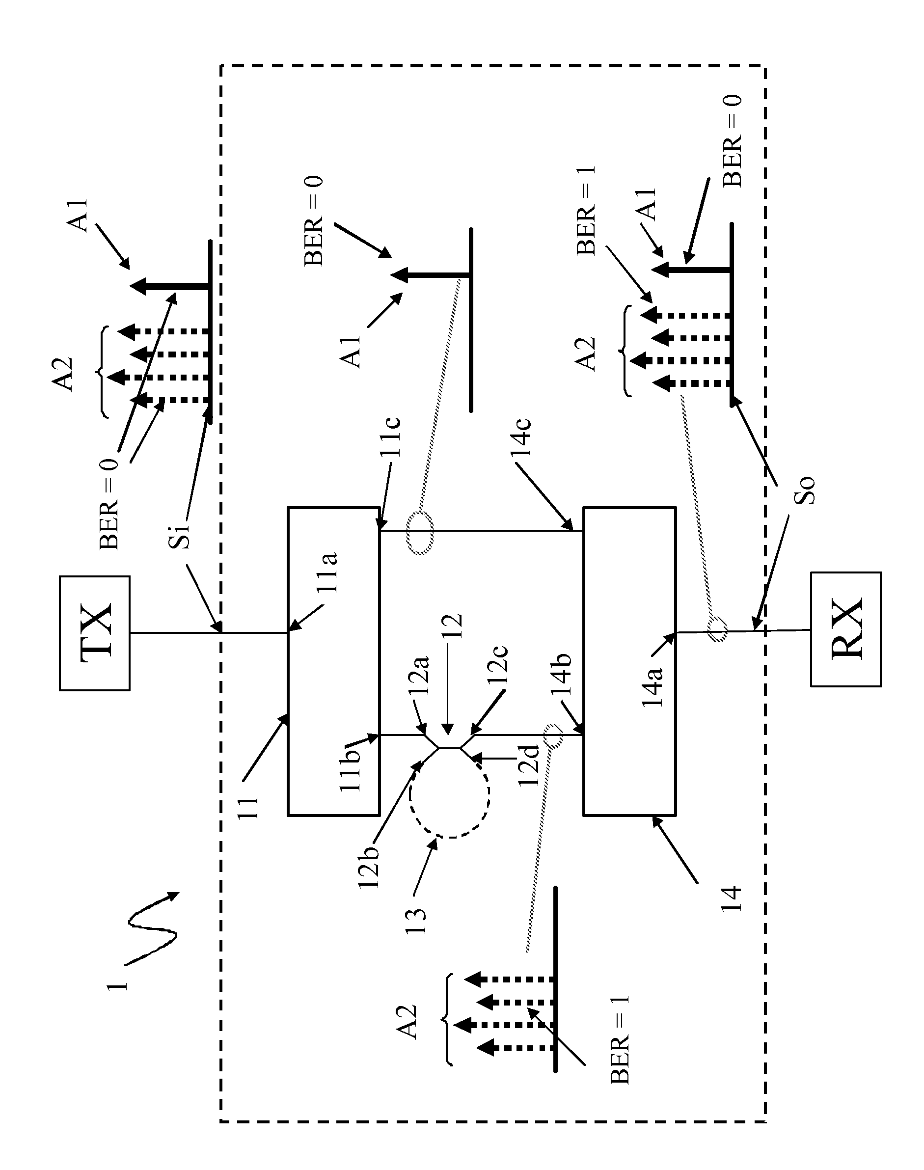
[0023]In the exemplary scheme of FIG. 1, there is shown a submerged optical unit 1 adapted for receiving an incoming optical signal Si transmitted by a transmitter stations TX and which comprises a plurality of wavelengths as schematically shown by means of arrows A1 and A2. The wavelengths are assumed to carry traffic data. In the FIGURE, one solid arrow A1 is shown as to represent a wavelength comprising data traffic (hereinafter referred to as wanted data) which is intended to be forwarded to a receiver station RX such that the receiver station is capable of receiving the wavelength and detecting the wanted data carried by such wavelength. Although in the FIGURE, A1 is shown—in an exemplary manner—to represent one wavelength (shown by one arrow), it is to be noted that in practice more than one wavelength may be received and forwarded to the receiver station.

[0024]Furthermore, a plurality of dotted arrows A2 are shown to represent a plurality of wavelengths which are comprised in...


PUM


Abstract

A method of transmitting optical signals in a submarine optical network and an optical unit for performing the method, the optical unit is configured for receiving an optical signal comprising a plurality of wavelengths where at least some of the wavelengths comprise traffic data. The optical unit includes a processor unit which is configured for scrambling the shape of at least one wavelength comprising traffic data of the optical signal so as to make said traffic data of said at least one wavelength undetectable for a receiver station.

Description

[0001]The present invention relates to optical submarine communications networks.BACKGROUND ART[0002]Optical submarine cables are used for transmitting optical signals. Such cables typically have a plurality of optical fiber pairs which are used for transmission of optical signals. In certain applications it may be required that different fiber pairs are allocated to different customers, such that the entire capacity in one fiber pair is allocated to one particular customer. In such a case, there is no possible access by other customers that are allocated other fiber pairs, to the fiber pair of that particular customer. However, in certain cases, the capacity inside one fiber pair may be shared between various customers. Typically, the fiber may carry various wavelengths, and each wavelength is intended for use of a separate customer. In such cases a wavelength add-drop branching unit is inserted in the system and thereby some wavelengths are routed towards a branch station. In subm...

Claims


Application Information

Patent Timeline
Patent Type & Authority Patents(United States)
IPC IPC(8): H04K3/00H04J14/02H04K1/04H04K1/06
CPCH04J14/0227H04K1/04H04K1/06H04J14/02
Inventor MARCEROU, JEAN-FRANCOISLAVAL, CARINEDUPONT, SEBASTIEN
Owner ALCATEL LUCENT SAS
Learn More