
Control device of variable pitch vanes in a turbomachine

a technology of variable pitch vanes and control devices, which is applied in the direction of machines/engines, mechanical apparatus, liquid fuel engines, etc., to achieve the effect of simple, effective and economical

Active Publication Date: 2012-05-15
SN DETUDE & DE CONSTR DE MOTEURS DAVIATION S N E C M A
View PDF6 Cites 8 Cited by
  • Summary
  • Abstract
  • Description
  • Claims
  • Application Information

AI Technical Summary

Benefits of technology

[0007]The invention has in particular for purpose to provide a simple, effective and economical solution to the problems of current art, by authorizing the mounting of the jack at a distance from the articulation point on the control ring.
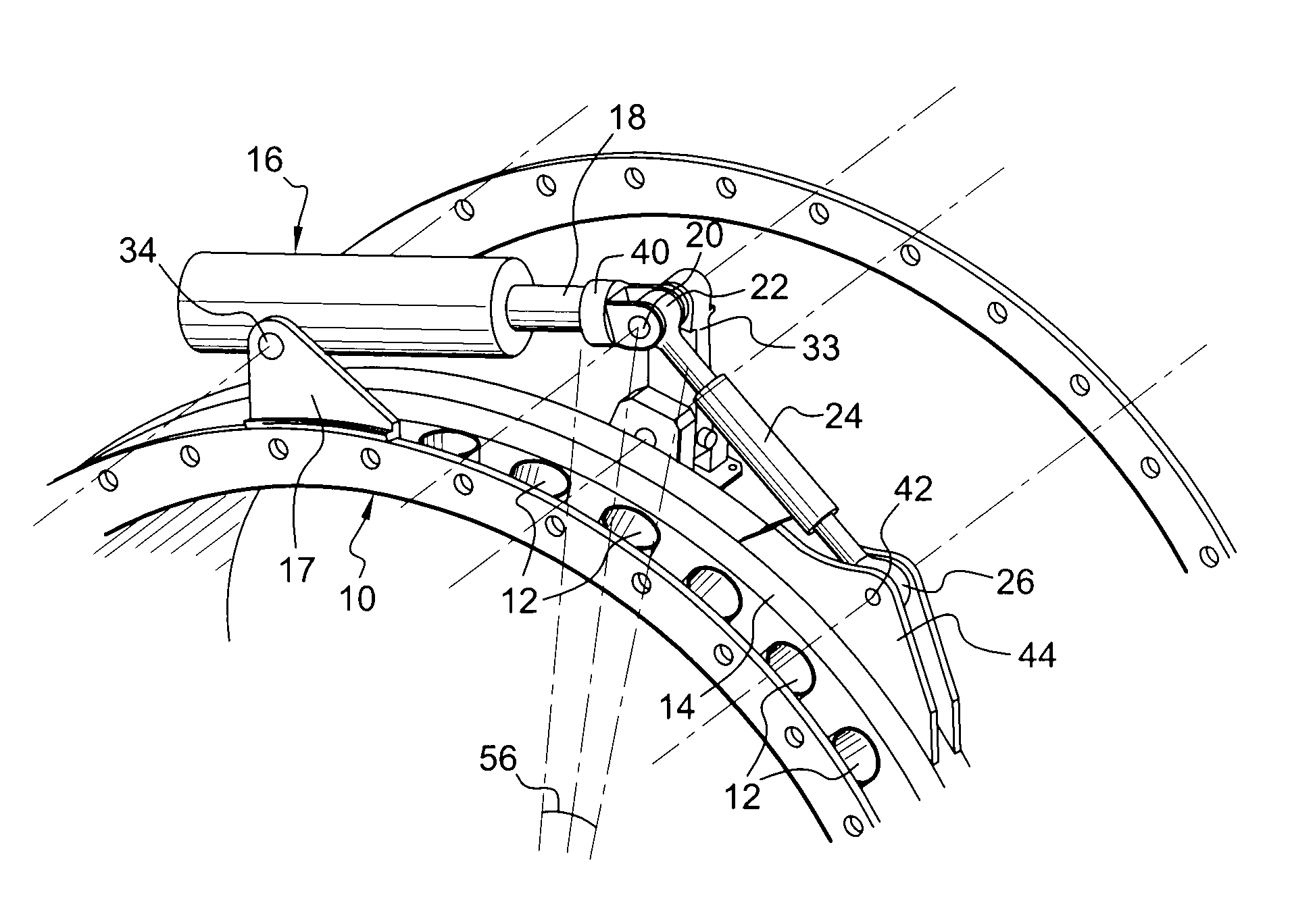
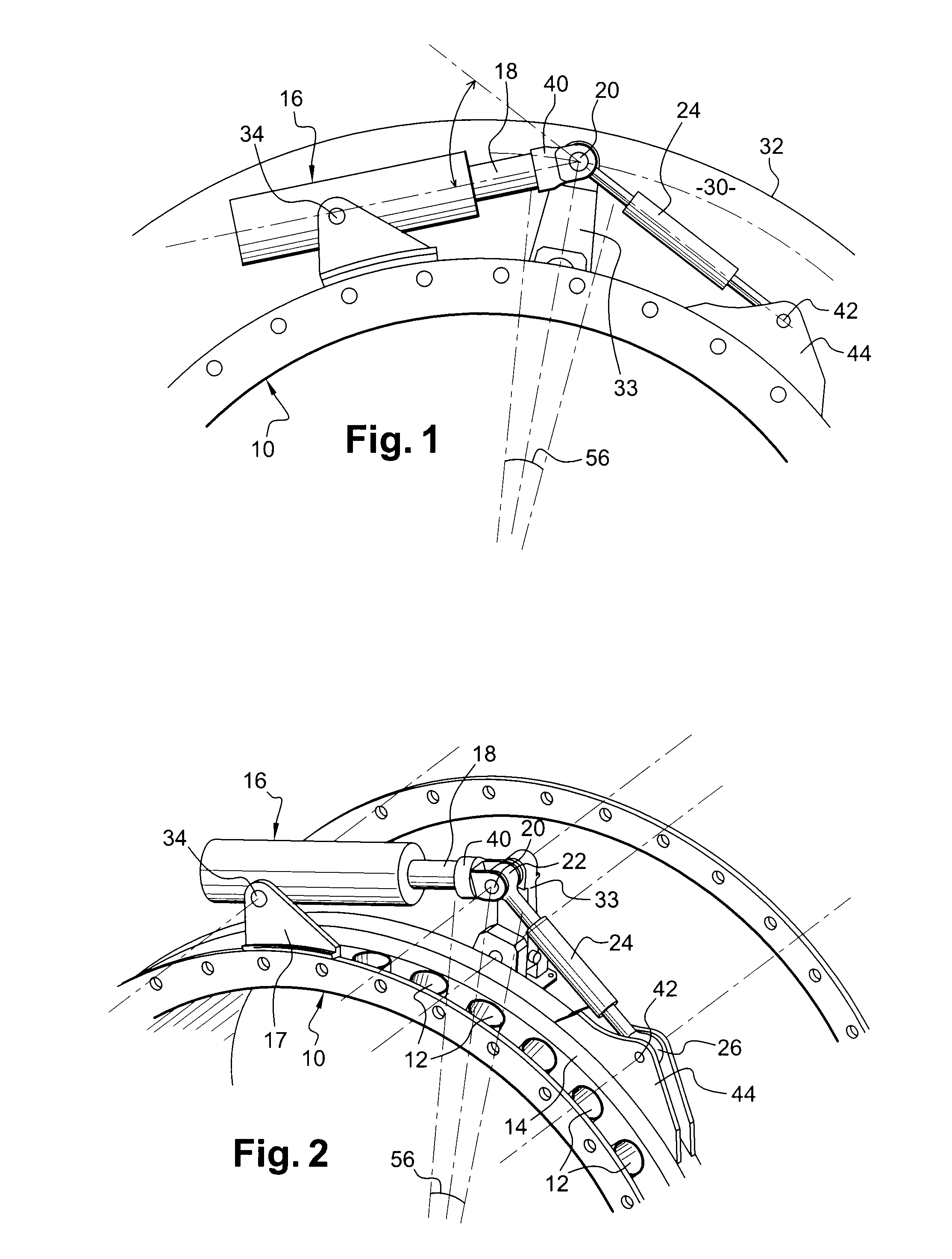
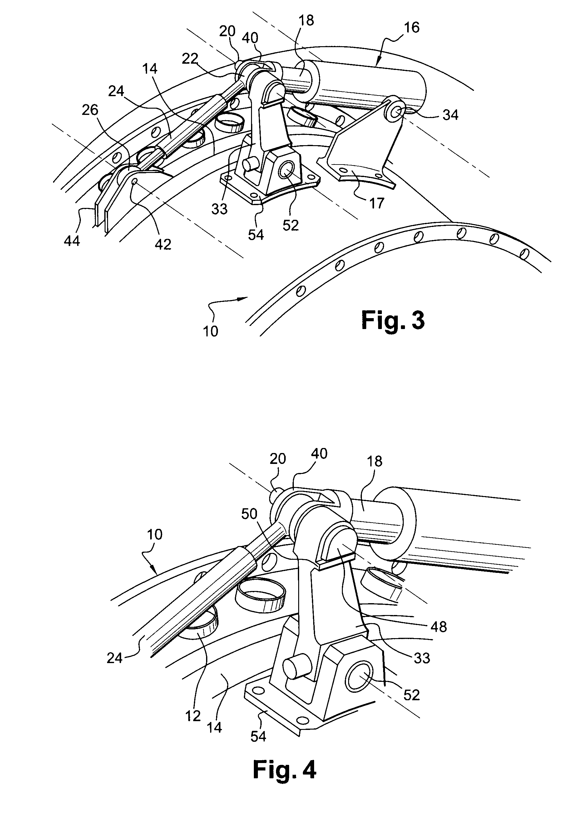
[0010]The invention furthermore makes it possible to mount the connecting rod in a perfectly tangential manner in relation to the ring, even if the misalignment between the axis of the jack and the connecting rod is 30° or more. The control device according to the invention can then be housed more easily in the annular space located between the casing and an external wall surrounding the casing and delimiting the passage stream of the secondary flow in the turbomachine.

Problems solved by technology

However, in this case, the misalignment of the axes of the jack and of the connecting rod can reach about 30°, and even more, which generates transverse forces that are too high on the rod of the jack during its displacements.

Method used


Image

  • Control device of variable pitch vanes in a turbomachine
  • Control device of variable pitch vanes in a turbomachine
  • Control device of variable pitch vanes in a turbomachine

Examples


Embodiment Construction

[0022]The control device of variable pitch vanes shown in FIGS. 1 to 4 is mounted on a substantially cylindrical casing 10 of a high-pressure compressor of a turbomachine such as an aircraft turbojet or turboprop engine.

[0023]The casing 10 bears one or several stages of variable pitch vanes which are not shown in the drawings, the vanes of one stage being distributed regularly around the revolving axis of the casing. In a known manner, each vane includes a blade connected at its radially external end to a radial cylindrical pivot which extends along the axis of rotation of the vane and which is engaged in a cylindrical duct 12 of the casing. The radially external end of this pivot is connected to the end of a link (not shown) of which the other end is connected to a ring 14 of the control device.

[0024]The ring 14 surrounds the casing 10 and can be displaced in rotation around the casing 10 by a jack 16 of the hydraulic, pneumatic or electrical type which is borne by supporting means...


PUM


Abstract

A control device of variable pitch vanes in a turbomachine is disclosed. The control device includes a ring surrounding a casing of the turbomachine and connected by links to the variable pitch vanes, and a jack connected to the ring in order to displace it in rotation around the casing. The jack is mounted pivoting on the casing and its piston rod is connected to the ring by a connecting rod. The piston and connecting rods are articulated on an axis which is connected to the casing by a guiding device maintaining it at a substantially constant distance from the casing.

Description

BACKGROUND OF THE INVENTION[0001]1. Field of the Invention[0002]This invention relates to a device for controlling variable pitch vanes in a turbomachine, such as an aircraft turbojet or turboprop engine.[0003]2. Description of the Related Art[0004]A turbomachine includes one or several stages of variable pitch straightening vanes which are mounted between rotor wheels of a compressor. These variable pitch vanes are borne by the stator of the turbomachine and can be adjusted in position around their axes in order to optimize the gas flow in the engine of the turbomachine.[0005]A variable pitch vane includes a cylindrical pivot at each of its ends, these pivots defining the axis of rotation of the vane. The radially external pivot is engaged in a cylindrical duct of a casing of the turbomachine and is connected by a link to a control ring driven in rotation around the casing by a jack. The rotation of the ring is transmitted by the links to the external pivots of the vanes and makes ...

Claims


Application Information

Patent Timeline
Patent Type & Authority Patents(United States)
IPC IPC(8): F01D17/00
CPCF01D17/162F04D29/563F05D2260/79F05D2260/50
Inventor BOURU, MICHEL ANDRE
Owner SN DETUDE & DE CONSTR DE MOTEURS DAVIATION S N E C M A
Learn More